The cup-shaped groove is a structural necessity for adhesion. When subjecting silicon-based PZT thick films to Cold Isostatic Pressing (CIP), a flat substrate is often insufficient to hold the material in place. The groove provides the physical confinement required to prevent the film from peeling off under high pressure.
Flat substrates typically fail to withstand the uneven forces and volume shrinkage inherent to the CIP process. The cup-shaped groove acts as a physical anchor, confining the PZT material and redistributing stress to prevent the film from detaching.
The Failure Mode of Flat Substrates
To understand why the groove is required, you must first understand why flat surfaces fail during this process.
Uneven Force Distribution
Cold Isostatic Pressing applies immense pressure to the material.
On a flat silicon substrate, this pressure is not always distributed evenly across the film. These irregularities create stress points that encourage separation between the film and the silicon.
Volume Shrinkage
As the PZT thick film is compressed, it undergoes volume shrinkage.
On a flat surface, there is no lateral support to accommodate or constrain this movement. This shrinkage creates shear forces at the interface, causing the film to pull away or peel off the substrate entirely.
How the Cup-Shaped Groove Solves the Problem
The solution lies in altering the geometry of the substrate using micromachining.
Physical Confinement
The groove changes the nature of the interface from a 2D surface to a 3D mold.
By etching a cup-shaped groove into the silicon, the PZT thick film is physically confined within the substrate. It is no longer sitting on the surface; it is sitting in the structure.
Structural Support
The walls of the groove provide necessary physical support that a flat surface lacks.
This support acts as a mechanical barrier, preventing the film from shifting or delaminating during the intense compression of the CIP process.
Stress Redistribution
The geometry of the groove alters how stress is applied to the film.
Rather than concentrating forces at the adhesion layer of a flat interface, the groove helps redistribute stress more effectively. This ensures the film remains intact despite the high pressure and shrinkage.
Understanding the Trade-offs
While the cup-shaped groove is effective, it introduces specific process requirements.
Increased Process Complexity
Implementing this structure requires an additional micromachining step.
You cannot simply deposit the film onto a standard wafer; you must first etch the specific cup-shaped grooves into the silicon substrate. This adds a layer of complexity to the fabrication process compared to using planar substrates.
Making the Right Choice for Your Goal
The use of cup-shaped grooves is a decision driven by the physics of adhesion and stress.
- If your primary focus is Film Integrity: You must utilize the cup-shaped groove structure to mechanically lock the film in place and prevent peeling during CIP.
- If your primary focus is Process Flow: Recognize that while etching grooves adds a step, it is a non-negotiable requirement for successful CIP processing of PZT on silicon.
The groove is not merely a design choice; it is the mechanical anchor that makes High-Pressure CIP viable for these materials.
Summary Table:
| Feature | Flat Silicon Substrate | Cup-Shaped Groove Structure |
|---|---|---|
| Adhesion Mechanism | Chemical/Surface only | Mechanical locking & 3D confinement |
| Stress Handling | High shear at interface | Stress redistribution through walls |
| Shrinkage Control | Unconstrained (peeling risk) | Physically constrained within mold |
| Fabrication | Simple / Standard | Requires micromachining/etching |
| CIP Suitability | Low (prone to failure) | High (ensures film integrity) |
Maximize Your Material Integrity with KINTEK Pressing Solutions
Don't let delamination or uneven stress compromise your research. KINTEK specializes in comprehensive laboratory pressing solutions tailored for advanced applications like battery research and PZT thick film development. Our diverse range—including manual, automatic, heated, and multifunctional models, alongside high-precision Cold and Warm Isostatic Presses—is designed to handle the most demanding structural requirements.
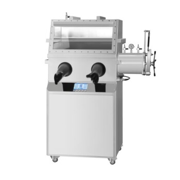
Whether you are working with complex micromachined substrates or require glovebox-compatible systems, our experts are ready to help you achieve perfect results. Contact KINTEK today to find the ideal press for your lab and take the next step in precision material engineering.
References
- Qiangxiang Peng, Dong-pei Qian. An infrared pyroelectric detector improved by cool isostatic pressing with cup-shaped PZT thick film on silicon substrate. DOI: 10.1016/j.infrared.2013.09.002
This article is also based on technical information from Kintek Press Knowledge Base .
Related Products
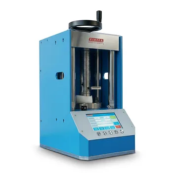
- Electric Lab Cold Isostatic Press CIP Machine
- Electric Split Lab Cold Isostatic Pressing CIP Machine
- Automatic Lab Cold Isostatic Pressing CIP Machine
- Manual Cold Isostatic Pressing CIP Machine Pellet Press
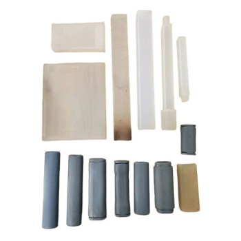
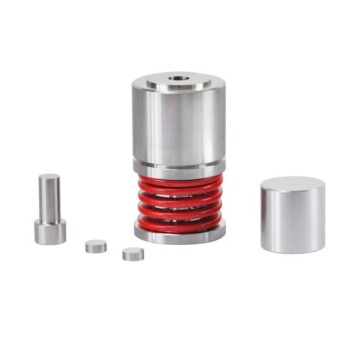
- Lab Isostatic Pressing Molds for Isostatic Molding
People Also Ask
- What are the characteristics of standard off-the-shelf electric lab CIP solutions? Achieve Immediate, Cost-Effective Processing
- What customization options are available for electric lab cold isostatic presses? Tailor Pressure, Size & Automation for Your Lab
- How does electrical Cold Isostatic Pressing (CIP) contribute to cost savings? Unlock Efficiency and Reduce Expenses
- What is the fundamental operating principle of an Electric Lab Cold Isostatic Press (CIP)? Achieve Superior Uniformity in Powder Compaction
- What is the Electric Lab Cold Isostatic Press (CIP) and its primary function? Achieve Uniform High-Density Parts