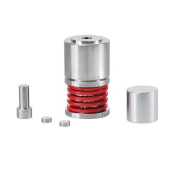
In Multi-Layer Ceramic Capacitor (MLCC) compression simulations, the primary function of a rubber sheet is to create a hyperelastic interface that models non-rigid boundary conditions. By introducing a thin layer (typically 100 micrometers) above the block, the simulation allows the contact surface to elastically deform, accommodating the sample's surface micromorphology and ensuring uniform pressure distribution.
The rubber sheet does not just transmit force; it changes the nature of the constraint. By allowing lateral freedom rather than enforcing a rigid boundary, it enables researchers to study specific displacement patterns that occur after the material reaches its compression saturation point.
Simulating Realistic Contact Mechanics
To accurately model the physical pressing process, simulations must account for how force is applied to the delicate ceramic layers.
Utilizing Hyperelastic Properties
The rubber sheet functions as a hyperelastic material. Instead of acting as a rigid wall, it deforms elastically under load.
This flexibility allows the sheet to conform to the microscopic irregularities of the MLCC surface.
Ensuring Uniform Pressure
Direct contact with a rigid tool can create stress concentrations on uneven surfaces. The rubber sheet acts as a buffer.
By conforming to the sample's surface micromorphology, the sheet ensures that pressure is applied evenly across the entire block, preventing artificial stress peaks in the simulation results.
Analyzing Material Behavior Under Load
Beyond simply applying pressure, the rubber sheet is a critical diagnostic tool for understanding how the MLCC block moves and deforms.
Permitting Lateral Freedom
Unlike rigid constraints, the rubber interface allows for lateral freedom at the sample surface.
This means the MLCC block is not locked in place horizontally; it can expand or shift slightly sideways as vertical pressure is applied.
Studying Saturation and Displacement
This configuration is specifically used to analyze lateral displacement patterns.
Researchers use this setup to observe sudden changes in displacement that occur after the block reaches a compression saturation point (such as 8% strain). This data is vital for understanding how the component behaves under non-rigid constraints.
Understanding the Trade-offs: Flexible vs. Rigid Boundaries
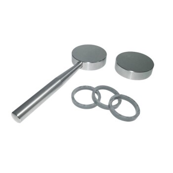
To choose the right simulation setup, you must understand how rubber sheets compare to other interface materials, such as thick PET films.
Rubber Sheets (Flexible Interface)
Rubber focuses on external deformation and lateral movement.
It is the superior choice when you need to understand surface interactions and displacement patterns under "soft" or variable constraints.
PET Films (Rigid Interface)
Thick PET films (e.g., 250 micrometers) act as carriers that simulate rigid boundary conditions.
As noted in supplementary data, PET films create a plane strain environment. This is better for analyzing how ceramic expansion absorbs internal electrode gaps, which is critical for optimizing the internal electrode area design.
Making the Right Choice for Your Simulation
Selecting the correct interface material depends entirely on the specific mechanical phenomenon you wish to isolate.
- If your primary focus is analyzing lateral displacement and surface mechanics: Use a rubber sheet to simulate non-rigid constraints and capture behavior after compression saturation.
- If your primary focus is optimizing electrode design and internal gap absorption: Use a thick PET film to enforce rigid boundary conditions and simulate plane strain.
By matching the interface material to your analytical goal, you ensure your simulation reflects the relevant physical reality of the manufacturing process.
Summary Table:
| Interface Material | Constraint Type | Primary Function | Ideal Application |
|---|---|---|---|
| Rubber Sheet | Non-Rigid / Flexible | Uniform pressure & lateral freedom | Surface micromorphology & saturation displacement |
| Thick PET Film | Rigid / Fixed | Plane strain environment | Internal electrode gap absorption & design optimization |
| Rigid Tooling | Absolute Rigid | Stress concentration | Baseline mechanical testing |
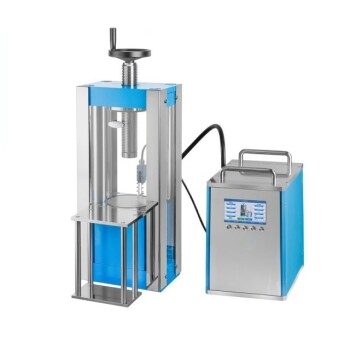
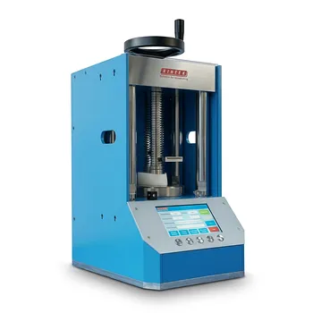
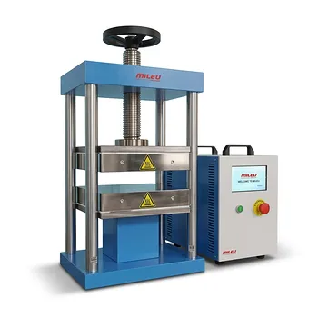
Optimize Your MLCC Manufacturing with KINTEK
Precision in simulation requires precision in execution. KINTEK specializes in comprehensive laboratory pressing solutions, offering manual, automatic, heated, multifunctional, and glovebox-compatible models, as well as cold and warm isostatic presses widely applied in battery and ceramic research.
Whether you are simulating rubber pressure processes or scaling up production, our advanced pressing equipment ensures the uniform force distribution and control your research demands.
Ready to enhance your lab's efficiency? Contact us today to find the perfect press for your application!
References
- Fumio NARUSE, Naoya TADA. OS18F003 Deformation Behavior of Multilayered Ceramic Sheets with Printed Electrodes under Compression. DOI: 10.1299/jsmeatem.2011.10._os18f003-
This article is also based on technical information from Kintek Press Knowledge Base .
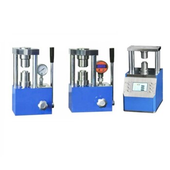
Related Products
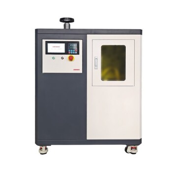
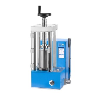
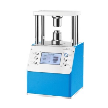
- Laboratory Hydraulic Press Lab Pellet Press Button Battery Press
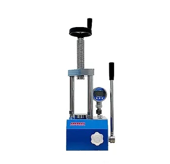
- Manual Laboratory Hydraulic Press Lab Pellet Press
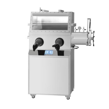
- Laboratory Hydraulic Press Lab Pellet Press Machine for Glove Box
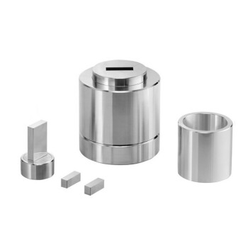
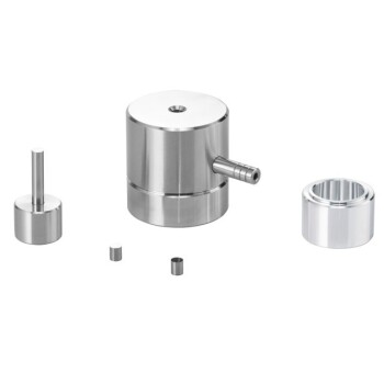
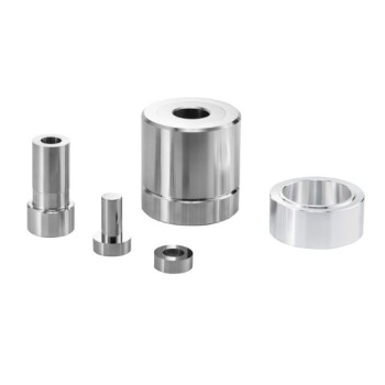
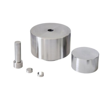
- Assemble Square Lab Press Mold for Laboratory Use
- Lab Round Bidirectional Press Mold
People Also Ask
- What role does a laboratory hydraulic press play in evaluating solid-state interfaces? Achieve Superior Densification
- What is the role of a laboratory hydraulic press in the green body quality control? Master Your Sintering Trajectory
- Why is the temperature control precision of a lab hydraulic press critical in micro-structure thermal forming?
- What role does a laboratory hydraulic press play in the assembly of all-solid-state battery test cells? Expert Guide
- What role does a laboratory hydraulic press play in the preparation of piezoelectric ceramic discs for DC-PG? | KINTEK