Precise gap control is the fundamental prerequisite for valid electrical characterization in oxide powder epoxy cells. By strictly maintaining a spacing of typically 4 to 5 mm between metal electrodes, you ensure that the oxide powder is distributed with geometric consistency. This physical uniformity is required to prevent structural irregularities from distorting the delicate electrical signals captured during testing.
Inconsistent geometry introduces artifacts that obscure the material's true properties. Precise gap control creates the necessary stable measurement plane, ensuring that surface potential readings accurately reflect the internal charge separation and chemical potential bias.
Establishing Geometric Consistency
The Role of the 4-5 mm Standard
In the construction of these cells, the distance between electrodes is not arbitrary. It is typically maintained at a specific range of 4 to 5 mm.
This dimension ensures the oxide powder is distributed evenly throughout the epoxy matrix. Without this standardization, the density and arrangement of particles would vary unpredictably across the sample.
Creating a Stable Measurement Plane
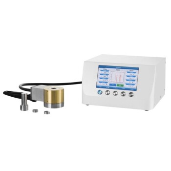
A uniform physical structure provides a flat, predictable surface for analytical instruments. This is particularly critical when utilizing high-sensitivity tools like scanning Kelvin probes.
The probe relies on a consistent distance from the sample surface to function correctly. Gap control ensures the "measurement plane" remains stable across the entire scanning area.
Ensuring Data Fidelity
Reflecting the Internal Physical State
The ultimate goal of testing is to understand the material's internal chemistry, specifically its charge separation and chemical potential bias.
If the cell construction is flawed, the data will reflect the cell's geometry rather than the material's properties. Precise gap control isolates the variables, ensuring the data represents the physics of the powder itself.
Validating Open-Circuit Conditions
Measurements are often taken under open-circuit conditions, where the system is most sensitive to external noise and structural variations.
By locking down the geometry, you guarantee that the captured surface potential is genuine. It confirms that voltage differences are caused by the material's electrochemical state, not by a fluctuating electrode gap.
Common Pitfalls and Trade-offs
The Risk of Geometric Artifacts
The primary trade-off in cell construction is the time required for precision versus the risk of data corruption. Rushing the assembly leads to variable gap widths.
If the gap varies, the electrical field distribution changes. This results in "geometric artifacts"—data points that look like chemical reactions but are actually just measurements of uneven construction.
Probe Misalignment
Scanning Kelvin probes are highly sensitive to surface topography.
If the gap control is poor, the resulting surface irregularities can confuse the probe. This leads to noisy data or false peaks in the potential map, rendering the test results unreliable.
Making the Right Choice for Your Experimental Setup
To ensure your testing yields actionable insights, you must prioritize mechanical precision during assembly.
- If your primary focus is data accuracy: Strictly enforce the 4-5 mm gap tolerance to eliminate geometric noise from your surface potential readings.
- If your primary focus is comparative analysis: Standardize the electrode spacing protocols across all batches to ensure that differences in data reflect material changes, not assembly variations.
Consistency in construction is the only path to clarity in measurement.
Summary Table:
| Feature | Specification | Impact on Electrical Testing |
|---|---|---|
| Standard Gap Distance | 4 to 5 mm | Ensures uniform oxide powder distribution and density. |
| Geometric Stability | High Precision | Creates a stable measurement plane for scanning Kelvin probes. |
| Data Fidelity | Artifact Prevention | Ensures readings reflect chemical potential, not physical flaws. |
| Measurement Mode | Open-Circuit | Maximizes sensitivity to internal charge separation states. |
Elevate Your Material Research with KINTEK Precision
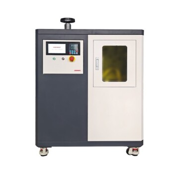
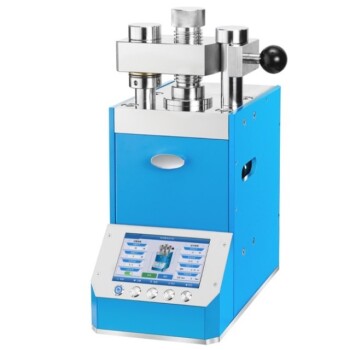
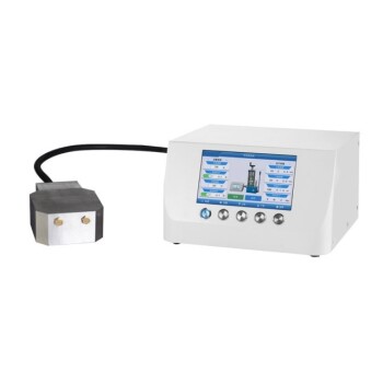
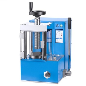
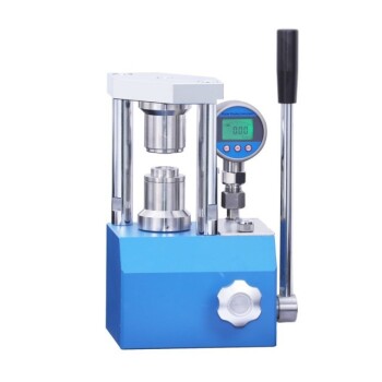
High-accuracy electrical characterization starts with flawless sample preparation. At KINTEK, we specialize in comprehensive laboratory pressing solutions designed to provide the geometric consistency your research demands. Whether you are conducting advanced battery research or exploring oxide powder electronics, our range of manual, automatic, heated, and multifunctional presses—including specialized isostatic models—ensures your samples meet the strictest tolerances.
Don't let geometric artifacts compromise your data fidelity. Partner with the experts in laboratory material processing to achieve perfectly standardized results every time.
Contact KINTEK Today to Find Your Ideal Pressing Solution
References
- Beatriz Moura Gomes, Maria Helena Braga. Polaronic and Electrochemical Signatures in Group IVB (Ti, Zr, Hf) Oxides: Unified SKP–DFT Insights for Tunable Transport in Energy and Electronic Devices. DOI: 10.1002/adfm.202509853
This article is also based on technical information from Kintek Press Knowledge Base .
Related Products
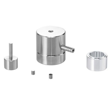
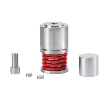
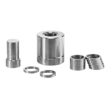
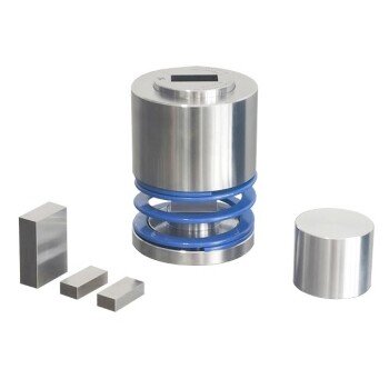
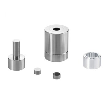
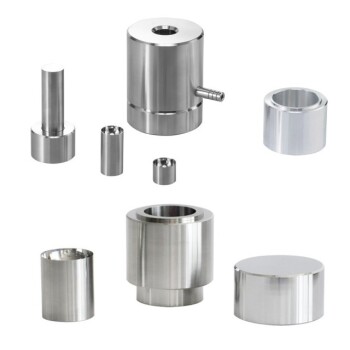
- Lab Cylindrical Press Mold for Laboratory Use
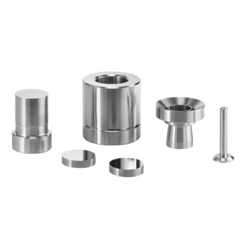
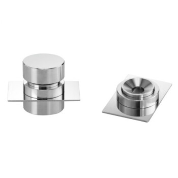
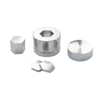
- Lab XRF Boric Acid Powder Pellet Pressing Mold for Laboratory Use
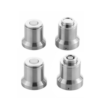
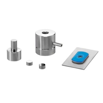
- Lab Button Battery Disassembly and Sealing Mold
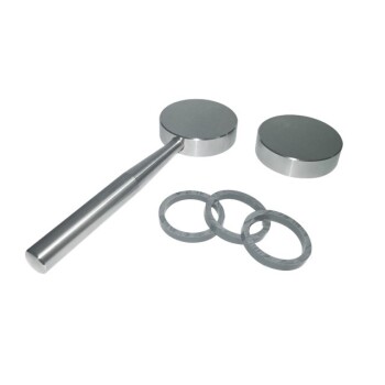
- XRF KBR Plastic Ring Lab Powder Pellet Pressing Mold for FTIR
- Lab Round Bidirectional Press Mold
People Also Ask
- Why are high-precision laboratory molds and specific compaction processes required? Ensure Data Integrity in Soil Research
- How does the geometry of laboratory molds influence mycelium-based composites? Optimize Density and Strength
- How do the design and geometric precision of pressing molds and mandrels affect the quality of PTFE composite samples?
- Why is a high-performance laboratory molding press critical for in-situ electrolyte formation? Unlock Battery Success
- What role do precision positioning and pressure molds play in single-lap joints? Ensure 100% Data Integrity