Precise compression control is the critical governing factor that determines the operational efficiency of porous electrode flow batteries. It is required to balance two competing physical necessities: establishing a low-resistance electrical connection while preserving the open structural void space needed for liquid electrolyte flow.
Core Takeaway Achieving the optimal performance in a flow battery requires a "Goldilocks" compression ratio—typically around 25%—to minimize electrical contact resistance without crushing the electrode's pores. This balance ensures that electrons can move freely into the current collector while electrolyte fluid can still permeate the electrode with minimal resistance.
The Engineering Challenge: Conductivity vs. Permeability
The carbon paper electrode serves two distinct functions in a flow battery assembly. The difficulty lies in the fact that improving one function through compression often degrades the other.
The Function of Compression
To function as an electronic conductor, the carbon paper must have intimate physical contact with the current collector (bipolar plate).
Applying pressure reduces the interfacial distance between these layers. This minimizes contact resistance, allowing electrons to flow efficiently out of the cell.
The Risk to Porosity
To function as a fluid transporter, the electrode must remain porous. The primary reference notes that a high internal compression porosity of approximately 85% is ideal.
Excessive force crushes the carbon fibers, reducing this porosity. This creates fluid transport resistance, making it difficult to pump electrolyte through the cell and starving the reaction sites.
The Mechanics of Optimal Compression
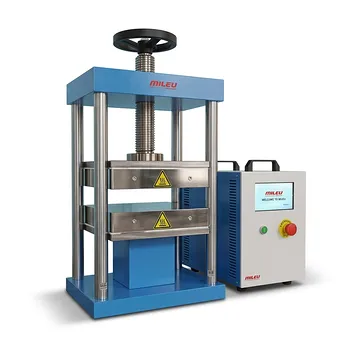
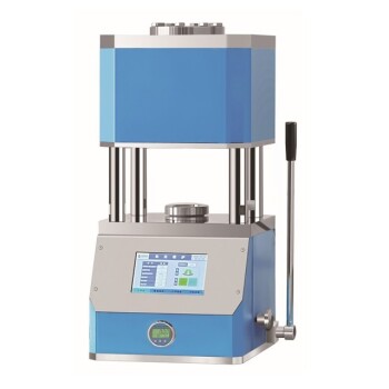
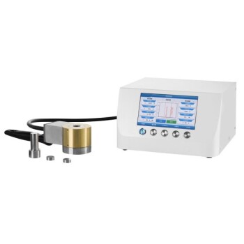
Engineers must use laboratory press machines or precision gaskets to target a specific geometry rather than simply applying maximum force.
The Target Compression Ratio
Research indicates that a compression ratio of approximately 25% is often the optimal target for carbon paper electrodes.
For example, this involves compressing a standard electrode sheet from an initial thickness of 280 μm down to 210 μm.
Improving Interfacial Contact
Controlled pressure eliminates microscopic gaps caused by surface roughness between the electrode and the current collector.
As highlighted in general battery assembly principles, this creates a seamless physical interface. This "unobstructed pathway" is essential for maximizing electronic conduction efficiency.
Understanding the Trade-offs
Failing to achieve precision in this assembly step results in two distinct failure modes. Understanding these helps in diagnosing performance issues during testing.
The Penalty of Under-Compression
If the compression ratio is too low (e.g., <15%), the electrode floats loosely against the current collector.
This results in high interfacial contact resistance. The battery will exhibit poor voltage efficiency because energy is lost as heat at the interface rather than being used for the electrochemical reaction.
The Penalty of Over-Compression
If the compression ratio is too high (e.g., >30%), the mechanical structure of the carbon paper collapses.
This creates an obstruction of conduction regarding the fluid transport. The pump must work harder to force electrolyte through the cell, and the active surface area becomes inaccessible, degrading rate performance.
Making the Right Choice for Your Goal
When designing your assembly protocol or choosing gasket thickness, your specific performance goals dictate the precise tolerance required.
- If your primary focus is Peak Power Density: Aim for the higher end of the compression tolerance (closer to 25-28%) to minimize electrical resistance, provided your pumps can handle the slight increase in pressure drop.
- If your primary focus is System Efficiency (Pumping Loss): Lean toward the lower end of the compression tolerance (closer to 20-22%) to maximize hydraulic permeability and reduce pumping energy costs.
Ultimately, the success of a flow battery assembly relies not on how tightly you clamp the cell, but on how precisely you maintain the electrode's internal geometry under load.
Summary Table:
| Metric | Under-Compression (<15%) | Optimal Compression (~25%) | Over-Compression (>30%) |
|---|---|---|---|
| Electrical Resistance | High (Poor contact) | Low (Excellent contact) | Minimal |
| Fluid Permeability | Maximum | Balanced (High porosity) | Low (Crushed pores) |
| Primary Risk | Voltage efficiency loss | N/A (Ideal Performance) | Pumping loss & starvation |
| Structural State | Loose/Gaps | Intimate Interface | Fiber Collapse |
Maximize Your Battery Research Precision with KINTEK
Achieving the perfect 25% compression ratio requires more than just force—it requires absolute control. KINTEK specializes in comprehensive laboratory pressing solutions designed for the rigorous demands of energy storage research.
Our range of manual, automatic, heated, and multifunctional presses, along with specialized cold and warm isostatic presses, provide the sub-micron precision necessary to optimize carbon paper electrodes without compromising their structural integrity. Whether you are working in a standard lab or a controlled glovebox environment, KINTEK ensures your flow battery assembly is consistent, repeatable, and efficient.
Ready to eliminate interfacial resistance and pumping losses?
Contact KINTEK Today for a Professional Consultation
References
- Emre Burak Boz, Antoni Forner‐Cuenca. Correlating Electrolyte Infiltration with Accessible Surface Area in Macroporous Electrodes using Neutron Radiography. DOI: 10.1149/1945-7111/ad4ac7
This article is also based on technical information from Kintek Press Knowledge Base .
Related Products
- Automatic Laboratory Hydraulic Press for XRF and KBR Pellet Pressing
- Laboratory Hydraulic Press 2T Lab Pellet Press for KBR FTIR
- Laboratory Hydraulic Pellet Press for XRF KBR FTIR Lab Press
- Laboratory Hydraulic Split Electric Lab Pellet Press
- Automatic Laboratory Hydraulic Press Lab Pellet Press Machine
People Also Ask
- What is the role of a laboratory pressure machine and KBr in FTIR? Master Sample Preparation for Flame Retardants
- Why is pressing powder into a pellet critical before sintering? Ensure Dense, Conductive Solid-State Electrolytes
- How does an automatic laboratory hydraulic press improve KBr pellet preparation? Achieve Precision IR Spectroscopy
- What are the advantages of using a laboratory automatic hydraulic press for HEA green compact forming?
- Why is an automatic laboratory hydraulic press essential? Unlock Precise Pressure for High-Performance Samples