Precise control of holding time is essential because it dictates the critical balance between optimizing the density of the electrode material and preserving the structural integrity of the substrate. In the context of flexible electrodes, holding time serves as a "tipping point" variable: too little results in poor particle contact, while too much causes irreversible damage to the conductive layers.
The holding time in Cold Isostatic Pressing (CIP) is not simply a matter of "longer is better." It is an optimization challenge where you must maximize the compaction of the thin film to improve energy conversion efficiency without fracturing the fragile Indium Tin Oxide (ITO) layer, which would drastically increase internal resistance.
The Role of Hydrostatic Pressure
Uniform Force Distribution
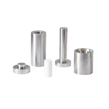
CIP utilizes flexible rubber molds as a pressure transmission medium. Because these molds possess high elastic deformation capabilities, they transfer high pressure uniformly across the entire surface of the material.
Preventing Structural Defects
This mechanism applies "hydrostatic pressure," meaning the force is equal from all directions. This allows the electrode material to achieve consistent compression rates, effectively preventing stress concentrations that typically lead to structural defects during the forming stage.
The Benefits of Optimized Holding Time
Enhancing Physical Contact
The primary goal of the holding phase is to ensure thorough compaction of the thin film. Sufficient holding time forces the particles into closer proximity, improving the physical contact between them.
Boosting Device Efficiency
For devices like flexible dye-sensitized solar cells (DSCs), this particle-to-particle contact is paramount. Improved compaction directly translates to higher final conversion efficiency for the device.
The Risks of Excessive Duration
Mechanical Damage to Substrates
While the pressure medium (rubber mold) is gentle, the duration of the pressure application introduces risk. Flexible electrodes often use plastic substrates coated with conductive layers, such as Indium Tin Oxide (ITO).
Increasing Internal Resistance
If the holding time extends beyond the optimal window, the stress on the substrate becomes destructive. This leads to mechanical damage of the conductive ITO layer. Once this layer is compromised, the internal resistance of the electrode spikes, degrading the overall performance of the cell.
Understanding the Trade-offs
The Threshold of Diminishing Returns
There is a specific limit where the benefits of compaction are overtaken by the penalties of damage. Evidence suggests that exceeding specific thresholds—such as 300 seconds at 200 MPa—markedly increases the risk of damaging the conductive layer.
Balancing Compaction vs. Conductivity
The operational challenge is to stay right at the edge of this threshold. You must hold pressure long enough to maximize density but release it before the stress fractures the ITO layer.
Making the Right Choice for Your Goal
To maximize the performance of flexible electrodes during CIP, you must treat holding time as a precision variable rather than a generic setting.
- If your primary focus is Electrical Conductivity: Prioritize shorter holding times (under 300 seconds at 200 MPa) to ensure the ITO layer remains intact and internal resistance remains low.
- If your primary focus is Film Density: Incrementally increase holding time to improve particle contact, but strictly monitor resistance metrics to detect the exact moment substrate damage begins.
Ultimately, the most effective process requires empirical testing to identify the exact second where compaction peaks immediately before substrate integrity fails.
Summary Table:
| Factor | Short Holding Time (< 300s) | Optimal Holding Time | Excessive Holding Time (> 300s) |
|---|---|---|---|
| Particle Contact | Poor / Incomplete | High / Maximized | Maximized |
| Substrate Integrity | Fully Preserved | Intact | Damaged (ITO Fractures) |
| Internal Resistance | Moderate | Low | Very High |
| Device Efficiency | Lower (Poor transport) | Peak Performance | Low (Circuit failure) |
| Primary Risk | Inadequate Compaction | None | Mechanical Stress Damage |
Maximize Your Electrode Performance with KINTEK
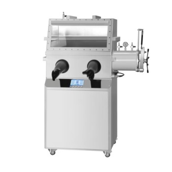
Precise pressure control is the difference between a high-efficiency cell and a fractured substrate. KINTEK specializes in comprehensive laboratory pressing solutions, offering manual, automatic, heated, multifunctional, and glovebox-compatible models, as well as cold and warm isostatic presses widely applied in battery research.
Our advanced CIP systems provide the precision timing and uniform hydrostatic pressure required to protect fragile ITO layers while achieving peak material density.
Ready to refine your electrode fabrication process? Contact us today to find the perfect CIP solution for your lab!
References
- Yong Peng, Yi‐Bing Cheng. Influence of Parameters of Cold Isostatic Pressing on TiO<sub>2</sub>Films for Flexible Dye-Sensitized Solar Cells. DOI: 10.1155/2011/410352
This article is also based on technical information from Kintek Press Knowledge Base .
Related Products
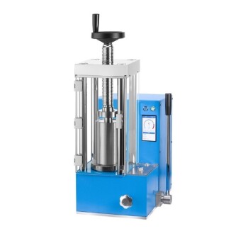
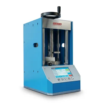
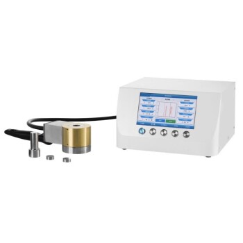
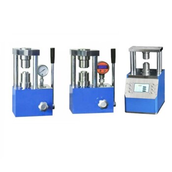
- Electric Lab Cold Isostatic Press CIP Machine
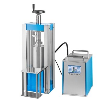
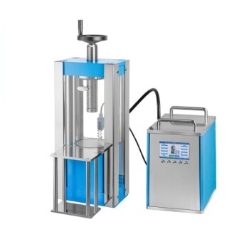
- Electric Split Lab Cold Isostatic Pressing CIP Machine
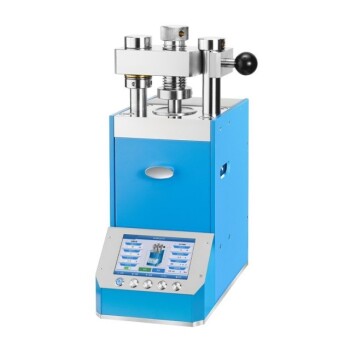
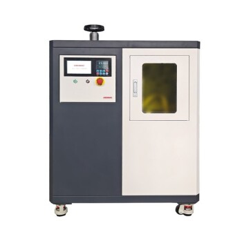
- Automatic Lab Cold Isostatic Pressing CIP Machine
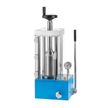
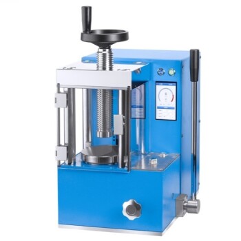
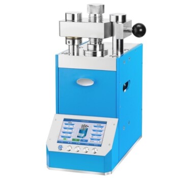
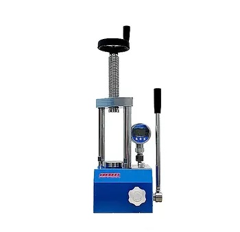
- Manual Cold Isostatic Pressing CIP Machine Pellet Press
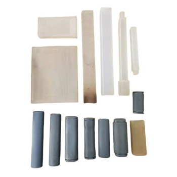
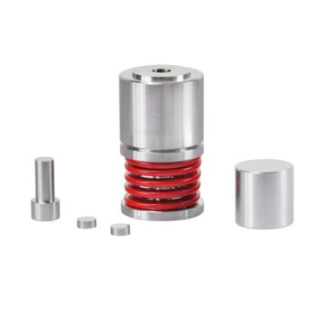
- Lab Isostatic Pressing Molds for Isostatic Molding
People Also Ask
- For what purpose are the high-pressure capabilities of electric lab cold isostatic presses used? Achieve Superior Density and Complex Parts
- What types of materials can be compacted using electric lab cold isostatic presses? Achieve Uniform Density for Metals, Ceramics & More
- What is the Electric Lab Cold Isostatic Press (CIP) and its primary function? Achieve Uniform High-Density Parts
- What role do electric lab cold isostatic presses play in industrial contexts? Bridge R&D and Manufacturing with Precision
- How does electrical Cold Isostatic Pressing (CIP) contribute to cost savings? Unlock Efficiency and Reduce Expenses