Separate measurement is mandatory because pressure molding induces structural anisotropy. When PW/EG (Paraffin Wax/Expanded Graphite) composites are compressed, the graphite layers are forced into a specific alignment rather than remaining random. This reorientation creates distinct thermal properties in the axial (transverse) and radial (longitudinal) directions, necessitating separate tests to accurately characterize the material's heat transfer capabilities.
The pressure molding process inherently alters the material's microstructure, creating a non-uniform distribution of graphite layers. Measuring conductivity in both directions is the only way to quantify the specific enhancement in heat transfer caused by this pressure-induced alignment.
The Impact of Processing on Microstructure
Pressure-Induced Alignment
Pressure molding is not a neutral process; it acts as a structural organizer. As force is applied, the expanded graphite layers within the composite are physically reoriented.
Creating Anisotropy
This process causes the material to adopt an anisotropic microscopic distribution. Instead of conducting heat equally in all directions (isotropy), the material develops a preferred direction for thermal flow based on how the graphite settles.
Distinguishing the Axes
To understand the material, you must distinguish between the transverse (axial) direction and the longitudinal (radial) direction. These vectors represent the distinct pathways heat can travel relative to the molding force applied during fabrication.
Quantifying Thermal Performance
Measuring Directional Differences
Because the structure is different in each direction, the thermal resistance will also differ. Testing both axes reveals the magnitude of these directional differences in thermal performance.
Assessing the Enhancement Effect
The primary goal of this measurement strategy is to quantify the enhancement effect. You need to determine exactly how much the pressure-induced alignment has improved conductivity in the longitudinal direction compared to the transverse direction.
Data for Optimization
This data is not merely academic; it is vital for application design. Without separate measurements, you cannot optimize the material's orientation within a thermal management system to leverage its most conductive pathway.
The Risks of Assuming Isotropy
Inaccurate Thermal Modeling
A common pitfall is assuming the composite conducts heat uniformly. If you measure only one direction and apply that value to the entire volume, your thermal simulations will likely fail to predict real-world overheating or inefficiency.
Misaligned Heat Sinks
Ignorance of directional conductivity leads to poor engineering decisions. You risk orienting the composite in a way that places the low-conductivity axis in the primary heat path, negating the benefits of the expanded graphite.
Making the Right Choice for Your Goal
To maximize the efficiency of PW/EG composites, you must apply this directional data to your specific engineering context.
- If your primary focus is Thermal Modeling: Ensure your simulation parameters account for anisotropic values, inputting distinct variables for X, Y (radial), and Z (axial) conductivity.
- If your primary focus is System Design: Orient the composite so that the radial (longitudinal) direction—typically the higher conductivity path—aligns with the primary direction of heat flow.
Understanding the directional nature of pressure-molded composites transforms them from simple materials into precision tools for thermal management.
Summary Table:
| Directional Axis | Orientation Relative to Molding | Structural Characteristic | Conductivity Impact |
|---|---|---|---|
| Axial (Transverse) | Parallel to molding force | Compressed graphite layers | Typically lower conductivity |
| Radial (Longitudinal) | Perpendicular to molding force | Aligned graphite pathways | Enhanced heat transfer pathway |
| Structural State | Pressure-induced alignment | Anisotropic distribution | Directional-dependent thermal resistance |
Optimize Your Thermal Research with KINTEK Precision
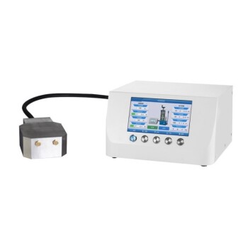
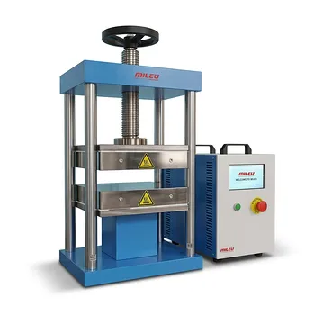
Accurate material characterization starts with controlled preparation. KINTEK specializes in comprehensive laboratory pressing solutions designed to help you achieve the precise structural alignment needed for advanced material studies. Whether you are developing battery technologies or advanced composites, our range of manual, automatic, heated, and multifunctional presses—including cold and warm isostatic models—ensures your samples meet the rigorous standards required for anisotropy analysis.
Don't let inaccurate thermal modeling hold back your innovation. Contact us today to find the perfect laboratory press for your research!
References
- Yilin Zhao, Haofeng Xie. Thermally Conductive Shape-Stabilized Phase Change Materials Enabled by Paraffin Wax and Nanoporous Structural Expanded Graphite. DOI: 10.3390/nano15020110
This article is also based on technical information from Kintek Press Knowledge Base .
Related Products
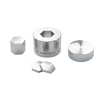
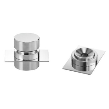
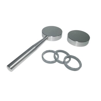
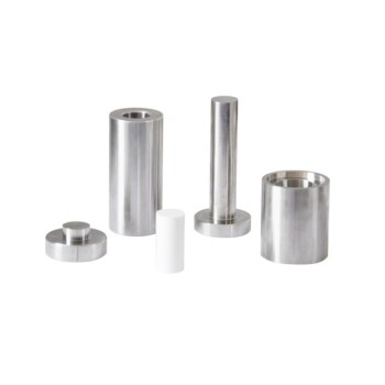
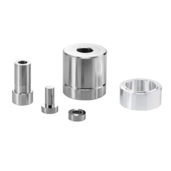
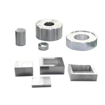
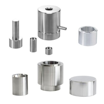
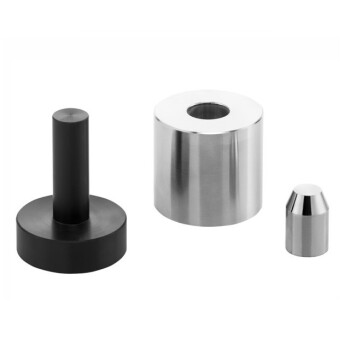
- Lab Polygon Press Mold
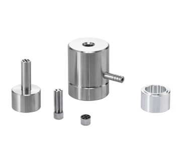
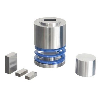
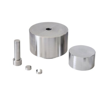
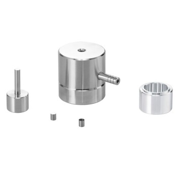
- Lab Round Bidirectional Press Mold
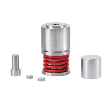
- Cylindrical Lab Electric Heating Press Mold for Laboratory Use
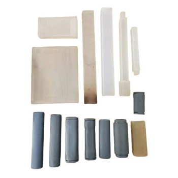
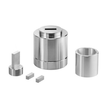
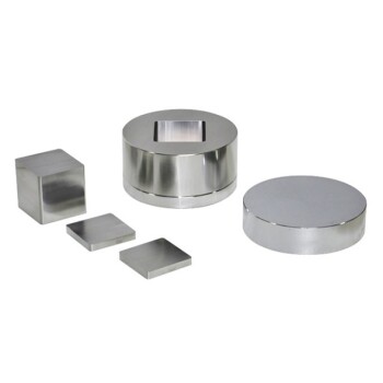
- Special Shape Lab Press Mold for Laboratory Applications
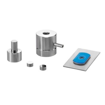
- Lab Infrared Press Mold for No Demolding
People Also Ask
- How does the geometry of laboratory molds influence mycelium-based composites? Optimize Density and Strength
- What is the significance of standardized molds in lab presses? Ensure Precise Seal Material Evaluation
- What role do precision positioning and pressure molds play in single-lap joints? Ensure 100% Data Integrity
- Why is precise cooling management of the lab press mold necessary? Protect Core Integrity in Thermoforming
- What are the requirements for pressing molds when using SSCG? Key Materials for Complex Single Crystal Production