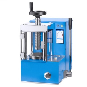
Laboratory hydraulic presses play a definitive role in sensor characterization by applying precise, controllable compressive stress. specifically within the range of 148 kPa to 926 kPa. This controlled environment allows engineers to correlate the sensor’s output voltage directly with known pressure inputs, establishing the baseline data required for performance analysis.
By systematically measuring response across different pressure levels, this testing establishes non-linear sensitivity models. These models are crucial for identifying how load transfer efficiency decays in silica crystals, ultimately dictating the valid measurement range of the sensor.
The Mechanics of Sensitivity Testing
Precise Stress Application
To accurately characterize a Biaxially Oriented Polyethylene Terephthalate (BOPET) sensor, you cannot rely on theoretical calculations alone. You need empirical data derived from physical stress.
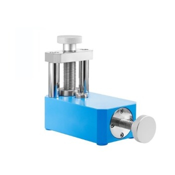
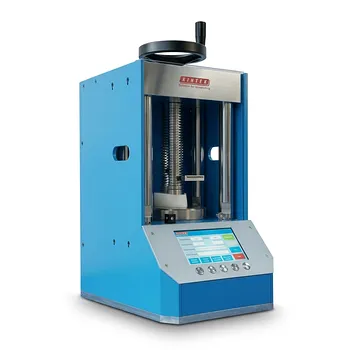
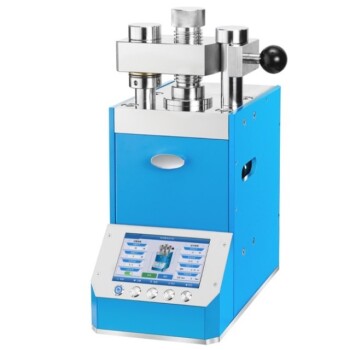
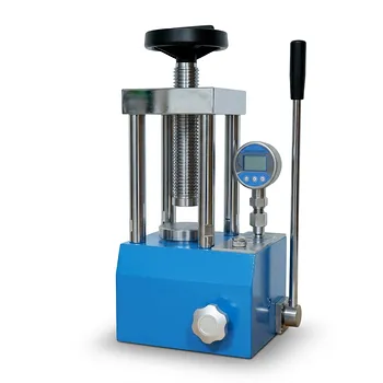
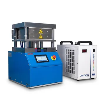
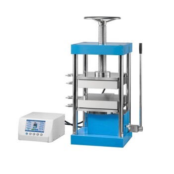
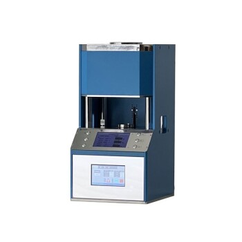
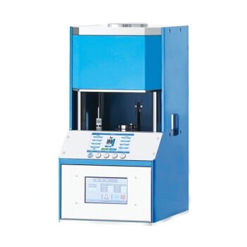
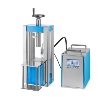
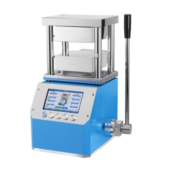
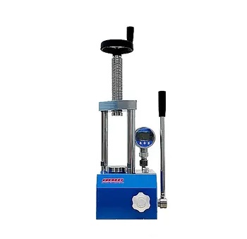
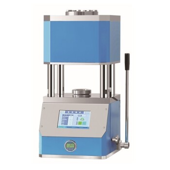
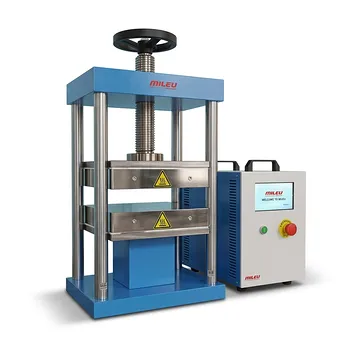
Laboratory hydraulic presses and pressure-loading devices provide the mechanism to apply this stress with high granularity.
The Critical Pressure Range
Current research focuses on a specific compressive stress window ranging from 148 kPa to 926 kPa.
Testing within this specific band ensures that the sensor is evaluated under realistic operating conditions.
Mapping Output Voltage
As the hydraulic press increases pressure, the device records the output voltage response of the sensor.
This creates a dataset that links specific physical loads to electrical signals, forming the foundation of the sensitivity curve.
Interpreting the Sensitivity Model
Establishing Non-Linear Models
The data collected from these tests rarely results in a perfectly straight line. Instead, it reveals a non-linear sensitivity model.
Understanding this non-linearity is vital for creating algorithms that can accurately interpret the sensor's readings in real-world applications.
Revealing Load Transfer Efficiency
The most critical insight provided by these tests involves the internal components of the sensor, specifically the silica crystals.
The sensitivity curves reveal decay patterns in load transfer efficiency.
Identifying Efficiency Decay
As pressure increases, the efficiency with which the silica crystals transfer load changes.
The hydraulic press tests visualize exactly when and how this efficiency begins to drop, providing a clear picture of the material's behavior under stress.
Understanding the Trade-offs
The Reality of Signal Decay
It is important to recognize that a sensor's sensitivity is not constant across its entire range.
The testing reveals that as high pressure is applied, the load transfer efficiency in the silica crystals eventually decays. This physical limitation means the sensor may become less responsive or less accurate at the upper limits of the tested pressure range.
Applying These Findings to Sensor Design
Guiding Measurement Range Design
The primary utility of these sensitivity curves is to define the sensor's operational limits.
By analyzing the decay patterns, researchers can scientifically determine the safe and accurate measurement range for the final device.
If your primary focus is Accuracy:
- Limit the sensor's operational range to the pressure levels before significant load transfer efficiency decay occurs.
If your primary focus is Durability:
- Use the high-pressure data (up to 926 kPa) to understand the mechanical limits of the silica crystals before failure or signal loss.
rigorous hydraulic press testing transforms raw voltage data into a reliable blueprint for sensor performance.
Summary Table:
| Parameter | Testing Range / Metric | Significance in Sensitivity Mapping |
|---|---|---|
| Compressive Stress | 148 kPa to 926 kPa | Defines the realistic operational window for testing |
| Output Metric | Voltage Response | Correlates physical load to electrical signals |
| Model Type | Non-linear Sensitivity | Essential for accurate sensor calibration algorithms |
| Internal Analysis | Silica Crystal Load Decay | Identifies efficiency loss and valid measurement limits |
Optimize Your Sensor Research with KINTEK
Precision is non-negotiable when establishing sensitivity curves for advanced BOPET sensors. KINTEK specializes in comprehensive laboratory pressing solutions designed to provide the granular control necessary for high-accuracy material testing.
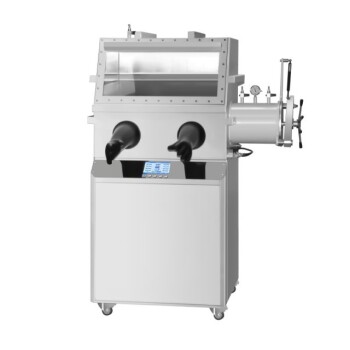
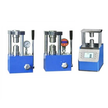
Whether you require manual, automatic, heated, or glovebox-compatible models, our equipment delivers the stable pressure application (148 kPa – 926 kPa and beyond) required to map load transfer efficiency and crystal decay accurately.
Ready to elevate your battery and material research? Contact KINTEK today to find the perfect hydraulic or isostatic press for your laboratory.
References
- Romana Stepancikova, Petr Slobodian. Pressure-Driven Piezoelectric Sensors and Energy Harvesting in Biaxially Oriented Polyethylene Terephthalate Film. DOI: 10.3390/s24041275
This article is also based on technical information from Kintek Press Knowledge Base .
Related Products
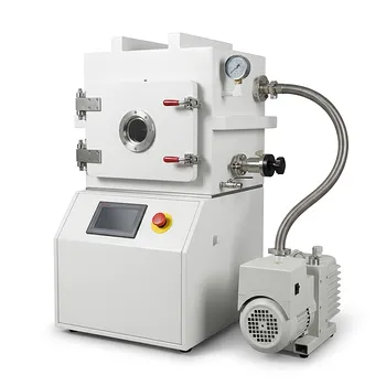
- Laboratory Hydraulic Press Lab Pellet Press Machine for Glove Box
- Laboratory Hydraulic Press 2T Lab Pellet Press for KBR FTIR
- 24T 30T 60T Heated Hydraulic Lab Press Machine with Hot Plates for Laboratory
- Laboratory Hydraulic Press Lab Pellet Press Button Battery Press
- Laboratory Hydraulic Pellet Press for XRF KBR FTIR Lab Press
People Also Ask
- How does the application of a laboratory hydraulic press improve the performance of Tungsten Trioxide (WO3) electrodes? - Pro Tips
- What role does a laboratory hydraulic press play in reaction pellets? Optimizing Lunar Soil and Metal Fuel Density
- Why Use a Laboratory Hydraulic Press for Li||LFP Battery Assembly? Optimize Interfacial Contact & Performance
- What is the function of a laboratory hydraulic press in FT-IR of curcumin-coated MWCNTs? Achieve Optical Clarity.
- What role does a laboratory hydraulic press play in the preparation of piezoelectric ceramic discs for DC-PG? | KINTEK