Multi-punch mold systems address density non-uniformity by enabling independent control over the pressing displacement for different sections of a part. Rather than applying a blanket force across a varied geometry, these systems match the specific displacement of each punch to the initial loading height of the corresponding section. This synchronization ensures that every area of the part, regardless of thickness or complexity, undergoes the same compression ratio.
The core issue with complex shapes is that standard molds compress varying thicknesses unevenly. Multi-punch systems solve this by creating a consistent compression ratio across the entire part, ensuring high density and structural uniformity.
The Challenge of Complex Geometries
The Limitation of Standard Molds
In a traditional Field Assisted Sintering Technology (FAST/SPS) setup, a single punch applies pressure to the powder. For flat, simple discs, this works perfectly.
The Problem with Varying Cross-Sections
However, when a part has steps, gears, or varying cross-sectional heights, a single punch fails. It compresses thinner sections more rapidly than thicker ones. This results in density gradients, where some areas are fully dense and others remain porous.
The Multi-Punch Solution
Independent Displacement Adjustment
Multi-punch systems break the molding process down into individual zones. The system allows for the independent adjustment of pressing displacement for different areas of the part.
Matching Displacement to Height
The key to this technology is precision. The system calibrates the movement of each punch based on the initial loading height of the powder in that specific section.
Targeted Compression
By isolating these sections, the mold ensures that a thicker section receives a proportional amount of displacement compared to a thinner section. This prevents the "shielding" effect where one part of the geometry absorbs the load intended for another.
Achieving Consistency via Compression Ratio
Defining the Goal
The ultimate goal in sintering is a homogeneous microstructure. To achieve this in complex parts, the compression ratio must be identical throughout the component.
How the System Delivers Uniformity
By precisely matching punch displacement to the local powder height, the multi-punch system forces a consistent compression ratio across the entire geometry. This ensures that density distribution remains uniform, regardless of the shape's complexity.
Understanding the Trade-offs
Increased Process Complexity
While effective, this method requires significantly more preparation than standard SPS. You must accurately calculate the initial loading heights to determine the correct displacement for each punch.
Precision Dependencies
The system relies entirely on the accuracy of the displacement matching. If the punch displacement does not perfectly correlate with the loading height, you may reintroduce the very density gradients you are trying to avoid.
Making the Right Choice for Your Goal
When deciding between standard tooling and a multi-punch system, consider the geometry of your final component.
- If your primary focus is simple, flat geometries: Utilize standard single-punch molds, as the complex setup of multi-punch systems provides no additional benefit.
- If your primary focus is complex parts with stepped cross-sections: distinct multi-punch systems are essential to prevent density variations and ensure mechanical integrity.
By mechanically enforcing a consistent compression ratio, multi-punch systems turn the production of complex geometries from a variable risk into a controlled process.
Summary Table:
| Feature | Single-Punch Mold | Multi-Punch Mold System |
|---|---|---|
| Geometry Support | Simple discs/flat shapes | Complex, stepped, or geared parts |
| Displacement Control | Uniform across the whole surface | Independent per section/zone |
| Compression Ratio | Variable (causes density gradients) | Consistent (uniform microstructure) |
| Setup Complexity | Low | High (requires precise calculations) |
| Density Profile | Non-uniform in varied thicknesses | Homogeneous throughout the part |
Elevate Your Material Research with KINTEK Precision Solutions
Struggling with density gradients in complex sintered parts? KINTEK specializes in comprehensive laboratory pressing solutions designed to overcome the most challenging geometries. From manual and automatic models to advanced isostatic, heated, and glovebox-compatible presses, we provide the precision tools necessary for cutting-edge battery research and material science.
Our value to you:
- Uniform Integrity: Achieve consistent compression ratios across varied cross-sections.
- Versatile Range: Specialized equipment for FAST/SPS, cold, and warm isostatic pressing.
- Expert Support: Solutions tailored to your specific powder loading and displacement needs.
Don't let geometry limit your innovation. Contact KINTEK today to find your perfect pressing solution and ensure every sample meets the highest standards of structural uniformity.
References
- Alexander M. Laptev, Olivier Guillon. Tooling in Spark Plasma Sintering Technology: Design, Optimization, and Application. DOI: 10.1002/adem.202301391
This article is also based on technical information from Kintek Press Knowledge Base .
Related Products
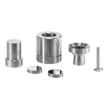
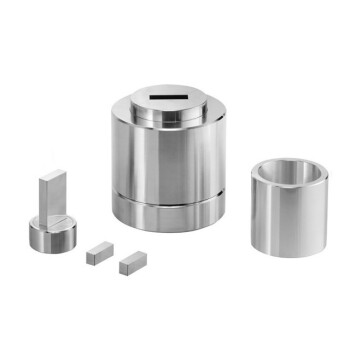
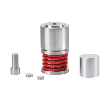
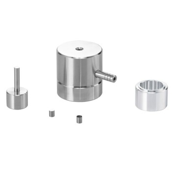
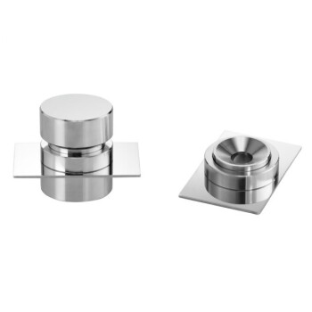
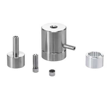
- Lab Button Battery Disassembly and Sealing Mold
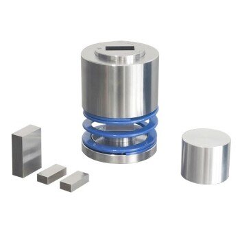
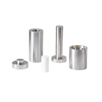
- Lab Ball Press Mold
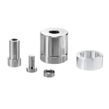
- XRF KBR Steel Ring Lab Powder Pellet Pressing Mold for FTIR
- XRF KBR Plastic Ring Lab Powder Pellet Pressing Mold for FTIR
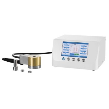
- Lab XRF Boric Acid Powder Pellet Pressing Mold for Laboratory Use
People Also Ask
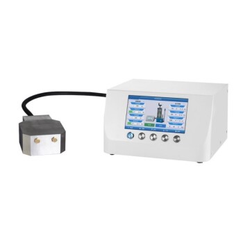
- How do laboratory battery sealing machines ensure performance consistency? Master Your Lithium and LFP Battery Assembly
- What is the function of a sealed reaction vessel in HATN-COF synthesis? Enhance Crystallinity & Pressure Control
- How do laboratory molding dies affect briquette quality? Master Precision and Material Choice
- What role do battery testing molds play in electrolyte performance? Exploring Pressure vs. Viscoelasticity
- Why are specialized battery test molds used? Ensure Peak Performance for All-Solid-State Sodium Batteries (ASSIBs)