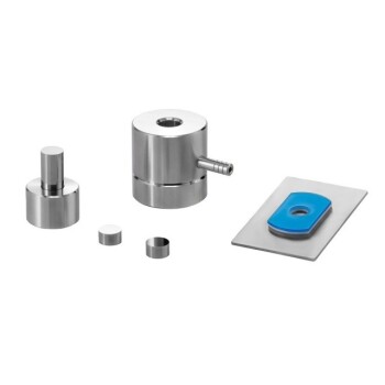
Mylar release films and alignment hole designs are not optional accessories; they are fundamental engineering controls required for the successful fabrication of Low-Temperature Co-fired Ceramic (LTCC) devices. Mylar films function as a protective interface that prevents the delicate ceramic "green" tapes from bonding to the mold or press plates, eliminating surface damage during separation. Simultaneously, alignment hole designs provide the essential geometric reference points needed to stack multiple layers with microscopic precision, ensuring that vertical electrical connections remain intact.
In LTCC manufacturing, process reliability depends on two distinct factors: surface quality and interlayer registration. Mylar films safeguard the physical integrity of the ceramic layers, while alignment holes guarantee the vertical accuracy required for complex electrical interconnects.
Preserving Substrate Integrity with Mylar
The Anti-Adhesion Barrier
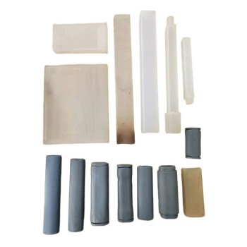
LTCC fabrication begins with "green tapes"—unfired ceramic sheets that are pliable and naturally prone to adhesion.
If these tapes come into direct contact with the metal surfaces of a mold or press plate during lamination, they will stick. Mylar release films act as a critical separator, preventing this unwanted bonding.
Ensuring Smooth Demolding
The process of removing the laminated stack from the mold (demolding) is a high-risk step for yield loss.
Without a release film, the mechanical force required to separate the ceramic from the mold could tear or warp the substrate. Mylar ensures the release is frictionless and smooth, preserving the surface quality of the green tape.
Achieving Electrical Continuity via Alignment Designs
Precision Through Mechanical Registration
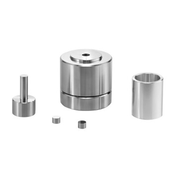
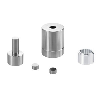
Alignment holes are designed to function in tandem with positioning pins within the mold tooling.
This system mechanically locks each layer of green tape into a specific X-Y coordinate before the stack enters the isostatic press. This prevents lateral shifting of the layers during the high-pressure lamination process.
Criticality for Interlayer Interconnects
LTCC devices are 3D circuits that rely on "vias"—vertical metallized channels—to connect different layers electrically.
If the layers are not perfectly aligned, these metallized vias will disconnect or "open," breaking the circuit. The alignment hole design is the primary mechanism for ensuring these vertical paths line up with sufficient accuracy to conduct electricity reliably.
Understanding the Operational Risks
The Consequence of Surface Defects
Neglecting the use of release films leads to immediate manufacturing bottlenecks. Molds must be cleaned frequently to remove residue, and the ceramic substrates often suffer from surface imperfections that render them unusable.
The Cost of Misalignment
The tolerance for error in LTCC stacking is incredibly low.
Even a microscopic misalignment caused by poor hole design or pin fit can sever electrical continuity. This results in functional failure of the final component, wasting material and processing time.
Making the Right Choice for Your Goal
To optimize your LTCC process, you must view these elements as critical to both yield and performance.
- If your primary focus is Manufacturing Yield: Prioritize high-quality Mylar films to eliminate scrap caused by sticking, tearing, or rough demolding.
- If your primary focus is Electrical Reliability: Invest strictly in precise alignment hole designs and tooling pins to ensure robust vertical connectivity for complex via structures.
The necessity of these components lies in their ability to transform a stack of soft ceramic sheets into a cohesive, electrically functional, and structurally sound device.
Summary Table:
| Feature | Primary Function | Manufacturing Benefit |
|---|---|---|
| Mylar Release Film | Anti-adhesion barrier | Prevents surface damage and ensures smooth demolding. |
| Alignment Holes | Mechanical registration | Guarantees vertical via continuity and prevents layer shifting. |
| Positioning Pins | Coordinate locking | Maintains X-Y accuracy during high-pressure lamination. |
| Green Tape Protection | Physical interface | Eliminates material waste from sticking or tearing. |
Elevate Your LTCC Fabrication with KINTEK Precision Tooling
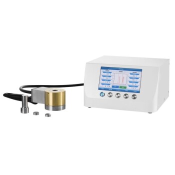
Don't let surface defects or misalignment compromise your 3D ceramic circuits. KINTEK specializes in comprehensive laboratory pressing solutions, offering a versatile range of manual, automatic, and heated presses, as well as cold and warm isostatic presses perfectly suited for advanced battery research and LTCC stacking. Our expertise ensures your delicate green tapes are processed with the exact pressure and alignment needed for high-yield manufacturing.
Ready to optimize your lab's efficiency? Contact us today to discover how our specialized molds and pressing technology can bring superior reliability to your research.
References
- Liyu Li, Zhaohua Wu. Effect of lamination parameters on deformation energy of LTCC substrate based on Finite element analysis. DOI: 10.2991/isrme-15.2015.317
This article is also based on technical information from Kintek Press Knowledge Base .
Related Products
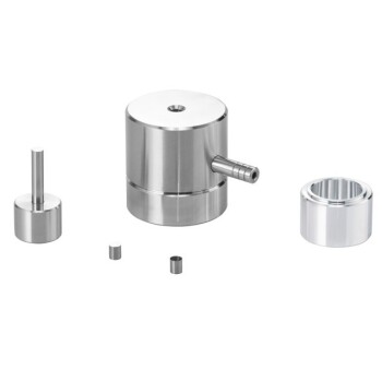
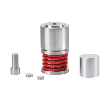
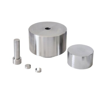
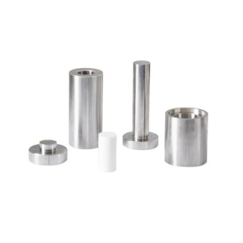
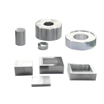
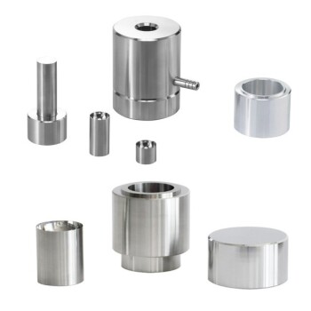
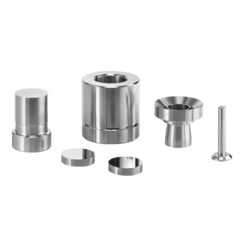
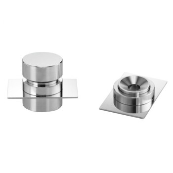
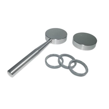
- Lab Cylindrical Press Mold for Laboratory Use
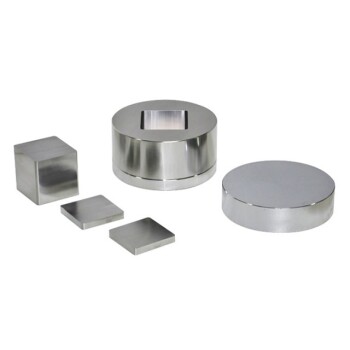
- Lab Double Plate Heating Mold for Laboratory Use
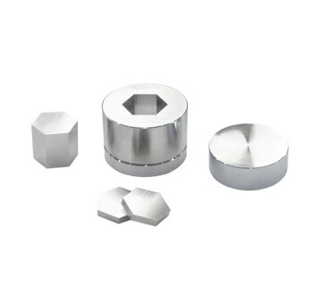
- Lab Round Bidirectional Press Mold
- Infrared Heating Quantitative Flat Plate Mold for Precise Temperature Control
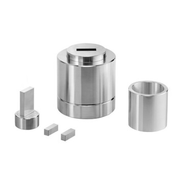
- Lab Anti-Cracking Press Mold
People Also Ask
- What role do precision positioning and pressure molds play in single-lap joints? Ensure 100% Data Integrity
- What is the purpose of incorporating cartridge heaters into a lab press mold for MLCC block compression? Optimize Results
- What is the function of a pressing tool in thermoplastic panels? Master Precision Shaping & Fusion Bonding
- Why are precision laboratory molds essential for forming basalt-reinforced lightweight concrete specimens?
- Why are high-precision laboratory molds and specific compaction processes required? Ensure Data Integrity in Soil Research