An industrial fluid loss tester functions by pressurizing cement slurry against a porous medium to simulate downhole stresses. Specifically, the device applies a controlled overpressure—typically around 690 kPa—to force the liquid phase of the slurry through a filter. The mechanism quantifies the volume of water lost over a specific timeframe, providing a direct simulation of how the material behaves in high-temperature and high-pressure (HTHP) environments.
The core purpose of this test is to predict how cement slurry retains water under pressure. By measuring fluid loss, you can ensure the material will not thicken prematurely or contaminate the surrounding geological formation, securing both construction safety and well integrity.
Simulating Downhole Conditions
The Application of Overpressure
The fundamental mechanism relies on a high-pressure chamber designed to mimic the hydrostatic pressure found in a wellbore.
The tester subjects the cement slurry to a specific overpressure, such as 690 kPa. This pressure acts as the driving force, attempting to push the mix water out of the suspension.
The Filtration Process
Inside the chamber, the slurry is pressed against a specialized filter medium.
This medium acts as a surrogate for the rock formation. It is permeable enough to allow water (filtrate) to pass through but fine enough to retain the solid cement particles, simulating the interface between the wellbore and the rock face.
Quantitative Volume Measurement
The output of the mechanism is a tangible volume measurement.
As pressure is maintained, the device collects the water that escapes the slurry. The total volume of this filtrate collected within a specified time indicates the slurry's ability to retain its water content.
Critical Implications for Performance
Preventing Premature Thickening
The mechanism is a critical check against slurry dehydration.
If the slurry loses water too rapidly through the filter, the water-to-cement ratio drops drastically. This causes the remaining slurry to thicken or set prematurely, which can lead to catastrophic pumping failures or pipe blockages.
Protecting the Production Formation
The test also predicts the impact on the surrounding environment.
High fluid loss means a significant amount of filtrate is entering the geological formation. This contamination can damage the production zone, potentially reducing the permeability of the rock and hindering future oil or gas extraction.
Understanding the Trade-offs
Static Simulation vs. Dynamic Reality
While the tester provides a standard baseline, it operates under static conditions.
Real-world cementing operations involve dynamic fluid flow and varying formation permeabilities. Therefore, the test results are an indicator of relative performance rather than an exact replication of every unique downhole scenario.
Interpreting Your Test Results
Correctly interpreting fluid loss data allows you to balance pumpability with formation protection.
- If your primary focus is Construction Safety: Ensure fluid loss is low enough to prevent the slurry from dehydrating and causing a "flash set" or blockage during pumping.
- If your primary focus is Reservoir Protection: Aim for minimal fluid loss to prevent filtrate from invading and damaging the porous structure of the production zone.
The fluid loss tester is your primary gatekeeper against backfill failure and reservoir contamination.
Summary Table:
| Key Mechanism Stage | Process Description | Critical Performance Metric |
|---|---|---|
| Overpressure Application | Applies ~690 kPa to mimic hydrostatic downhole stress | Driving force for fluid separation |
| Filtration Interface | Slurry pressed against a porous medium (rock surrogate) | Particle retention vs. liquid escape |
| Volume Measurement | Quantitative collection of filtrate over a set time | Fluid loss rate and slurry stability |
| Safety Check | Prevents dehydration and premature thickening | Avoids pump failure and blockages |
Elevate Your Laboratory Precision with KINTEK
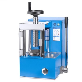
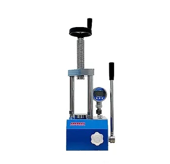
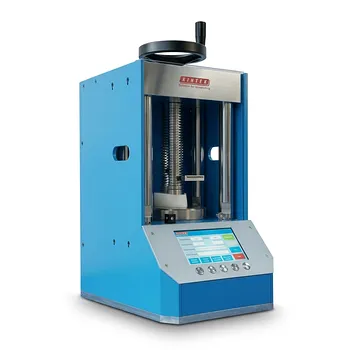
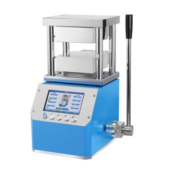
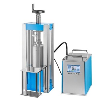
Maximize the reliability of your material testing with KINTEK’s comprehensive laboratory pressing solutions. Whether you are conducting critical cement slurry analysis for well integrity or advancing battery research, our range of manual, automatic, heated, and multifunctional models—including specialized cold and warm isostatic presses—delivers the controlled pressure and thermal accuracy your research demands.
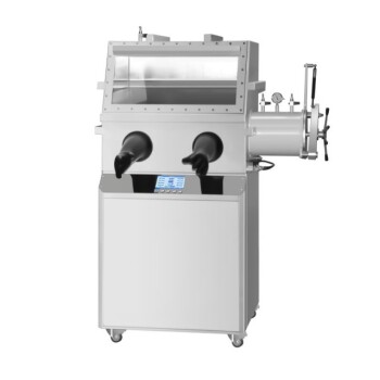
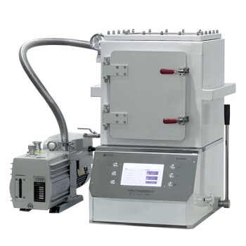
Don't compromise on simulation accuracy. Our glovebox-compatible systems and high-pressure testers are designed to help you prevent formation damage and ensure construction safety.
Contact KINTEK today to find the perfect press for your application!
References
- V. V. Nikishin, D. S. Kuznetsova. Investigation of Cement Compositions of Backfill Systems for Lining Wells with Inclined and Horizontal Sections. DOI: 10.5829/ije.2026.39.05b.06
This article is also based on technical information from Kintek Press Knowledge Base .
Related Products
- Laboratory Hydraulic Pellet Press for XRF KBR FTIR Lab Press
- Laboratory Hydraulic Press Lab Pellet Press Machine for Glove Box
- Manual Laboratory Hydraulic Press Lab Pellet Press
- Automatic Laboratory Hydraulic Press Lab Pellet Press Machine
- Manual Cold Isostatic Pressing CIP Machine Pellet Press
People Also Ask
- Laboratory Pellet Press for Solar PV Recycling: Ensuring High-Precision Material Analysis and Purity
- Why use a laboratory pellet press for solid-state battery evaluation? Ensure Accuracy in Interface Stability Testing
- Why is a laboratory pellet press used to pre-press BaSnF4 samples? Ensure Precision in High-Pressure Studies
- What is the necessity of a laboratory pellet press for alcohol by-product fuels? Maximize Energy Density & Consistency
- Why is high consistency in holding pressure from a laboratory pellet press required when preparing multi-component alloy specimens?