Pelletizing and sieving Bi–Mo–Co–Fe–O catalysts to a specific size range of 300–450 μm is a critical mechanical step that ensures both hydrodynamic stability and data accuracy within the reactor. By standardizing the particle size, you optimize the pressure drop across the bed and eliminate physical irregularities that cause uneven gas flow. This preparation allows you to capture the true chemical performance of the catalyst without interference from physical transport limitations.
Controlling particle size is about isolating the chemistry from the physics. It ensures that your spatial profile measurements reflect the catalyst's intrinsic kinetic characteristics, rather than being distorted by diffusion interference or inconsistent flow patterns.
Optimizing Reactor Hydrodynamics
Regulating Pressure Drop
The physical structure of the catalyst bed dictates how easily gas flows through it. By targeting the 300–450 μm range, you create a packed bed with consistent void space.
This optimizes the pressure drop, ensuring the system remains stable while allowing reactants sufficient contact time with the active sites.
Preventing Gas Channeling
When catalyst powder is irregular or loosely packed, gas will naturally seek the path of least resistance. This leads to gas channeling, where reactants bypass large sections of the catalyst bed entirely.
Sieving to a standardized size ensures the bed is uniform. This forces the gas to distribute evenly, maximizing efficiency and preventing physical instability.
Ensuring Data Integrity
Eliminating Concentration Polarization
In a non-uniform bed, reactants can build up in some areas while being depleted in others. This phenomenon is known as local concentration polarization.
Standardized particles ensure a uniform gas distribution. This homogeneity guarantees that the reactant concentration remains consistent relative to the flow, preventing localized "dead zones" or "hot spots."
Isolating Intrinsic Kinetics
The ultimate goal of testing these catalysts is often to understand their reaction rates. However, physical factors like mass transfer speed can mask the true chemical speed.
If particles are too large or irregular, measurements may reflect physical diffusion interference rather than the reaction itself. The 300–450 μm range ensures you are measuring the intrinsic kinetic characteristics of the Bi–Mo–Co–Fe–O structure.
Understanding the Trade-offs
Balancing Diffusion and Pressure
The selection of 300–450 μm represents a calculated balance. It is a "Goldilocks" zone for this specific catalyst application.
Risks of Deviating from the Range
If particles are significantly larger than this range, internal diffusion limitations may skew your kinetic data. Conversely, if particles are much smaller, the pressure drop may become too high for standard process stability.
Making the Right Choice for Your Goal
To apply this to your specific reactor setup or experimental design, consider your primary objective:
- If your primary focus is Kinetic Modeling: Prioritize strict sieving to the 300–450 μm range to ensure your data reflects chemical reaction rates, not diffusion limits.
- If your primary focus is Process Stability: Ensure the particle size distribution is narrow to prevent channeling and maintain a predictable pressure drop across the reactor.
Standardizing your catalyst geometry is the first line of defense against ambiguous experimental data.
Summary Table:
| Factor | Significance of 300–450 μm Range | Impact on Process/Data |
|---|---|---|
| Pressure Drop | Creates consistent void space in the packed bed | Ensures system stability and optimal contact time |
| Gas Flow | Prevents gas channeling (path of least resistance) | Maximizes catalyst efficiency and uniform distribution |
| Data Integrity | Eliminates local concentration polarization | Prevents localized dead zones and hot spots |
| Kinetic Accuracy | Minimizes physical diffusion interference | Isolates the catalyst's intrinsic chemical reaction rates |
Elevate Your Catalyst Research with KINTEK Precision
Achieving the perfect 300–450 μm particle size for your Bi–Mo–Co–Fe–O catalysts requires reliable laboratory equipment. KINTEK specializes in comprehensive laboratory pressing solutions designed for battery research and material science.
Our range includes:
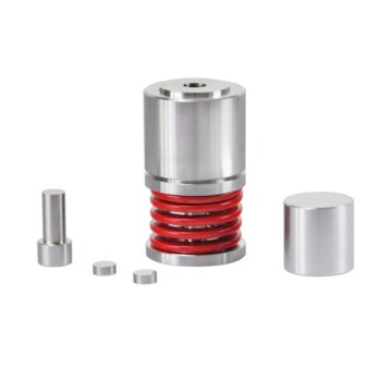
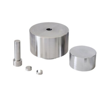
- Manual & Automatic Presses: For consistent pelletizing and structural integrity.
- Heated & Multifunctional Models: To meet specific material synthesis requirements.
- Isostatic Presses (Cold/Warm): For uniform density in advanced material preparation.
Don't let physical transport limitations mask your chemical breakthroughs. Contact KINTEK today to find the ideal pressing solution for your lab and ensure your data reflects true kinetic performance.
References
- Linda Klag, Jan‐Dierk Grunwaldt. Exploring structure, temperature and activity correlations in the selective oxidation of lower olefins over Bi–Mo–Co–Fe–O catalysts by spatial reactor profile measurements. DOI: 10.1039/d3cy01445b
This article is also based on technical information from Kintek Press Knowledge Base .
Related Products
People Also Ask
- Why is precise cooling management of the lab press mold necessary? Protect Core Integrity in Thermoforming
- What role do precision positioning and pressure molds play in single-lap joints? Ensure 100% Data Integrity
- What is the function of a pressing tool in thermoplastic panels? Master Precision Shaping & Fusion Bonding
- Why is a high-performance laboratory molding press critical for in-situ electrolyte formation? Unlock Battery Success
- What are the common applications for laboratory presses? Expert Guide to Sample Prep, R&D, and Quality Control