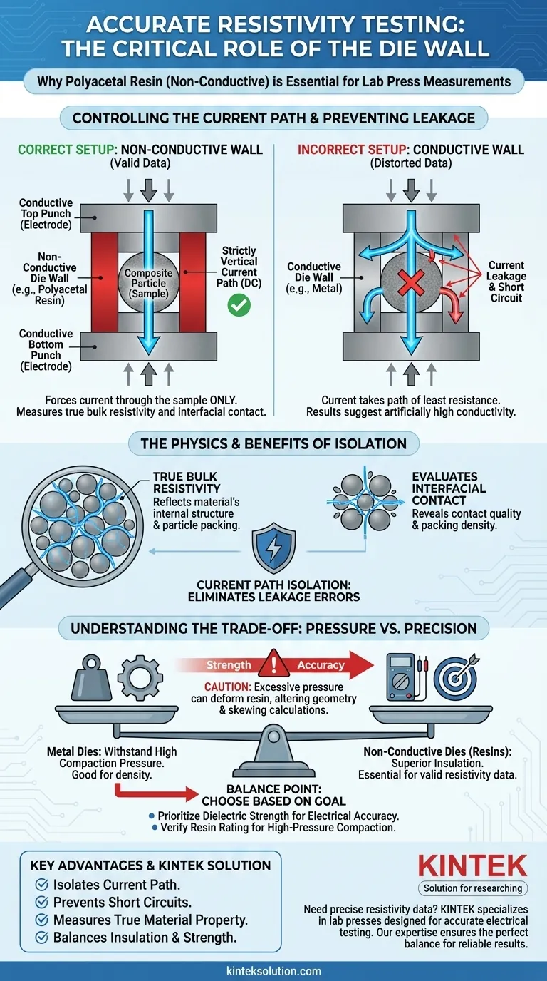
The die's side wall must be non-conductive to strictly define the path of the electrical current during measurement. If the side wall were conductive, the current would bypass the composite pellet and flow through the die itself, creating a short circuit. Using an insulating material like polyacetal resin forces the direct current (DC) to travel vertically through the sample, ensuring the data reflects the material's actual resistance rather than the equipment's properties.
Accurate resistivity testing relies entirely on current path isolation. By using a non-conductive die wall, you eliminate current leakage and ensure the measured resistance is a result of the composite material’s internal structure and particle interfaces.
The Physics of the Measurement Setup
Controlling the Current Path
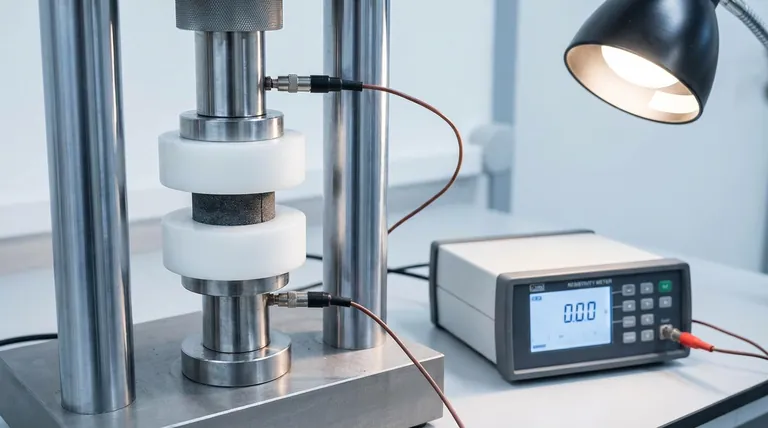
To measure resistivity accurately, the testing environment must be essentially a closed circuit containing only the sample.
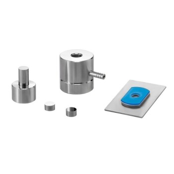
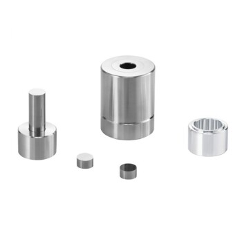
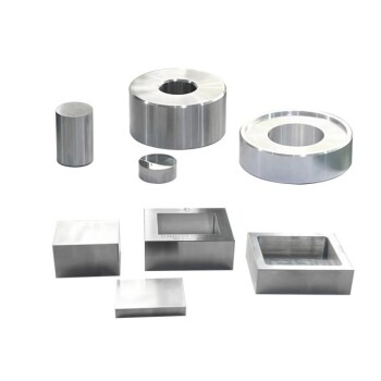
In this setup, the upper and lower punches are conductive (typically stainless steel) and act as the electrodes. The non-conductive side wall acts as a barrier.
This configuration forces the electrical current to flow in a strictly vertical path. It enters through the top punch, travels through the compacted pellet, and exits through the bottom punch.
Preventing Current Leakage
Electricity naturally follows the path of least resistance.
If the die wall were made of metal, it would likely offer lower resistance than the composite particle pellet. The current would "leak" into the walls, effectively flowing around the sample.
This leakage distorts the results, resulting in a reading that suggests the material is more conductive than it actually is.
Why Material Characterization Depends on Insulation
Measuring True Bulk Resistivity
The goal of this test is to determine bulk resistivity, which is an intrinsic property of the pellet's volume.
To calculate this, you need to know the exact cross-sectional area and length of the path the current traveled.
If the current leaks into the walls, the effective area becomes unknown. A non-conductive wall guarantees that the measurement volume matches the physical dimensions of the pellet.
Evaluating Interfacial Contact Properties
In composite particle pellets, resistivity is heavily influenced by how well the individual particles touch each other.
This is known as interfacial contact. High resistance often indicates poor contact between particles or gaps in the compaction.
If current leaks through the die wall, it masks these internal structural nuances. You lose the ability to analyze how the packing density and particle arrangement affect the material's conductivity.
Understanding the Trade-offs
Mechanical Limits of Non-Conductive Materials
While materials like polyacetal resin are electrically superior for this application, they often lack the mechanical hardness of steel.
Metals can withstand immense pressure without deformation. Resins may deform or wear out faster under high-pressure compaction.
Balancing Pressure and Precision
This creates a trade-off between the pressure you can apply and the accuracy of the electrical data.
You must ensure the pressure used to compact the pellet does not exceed the mechanical yield strength of the non-conductive die. Excessive pressure could crack the resin or cause it to expand, altering the pellet's geometry and skewing the resistivity calculation.
Making the Right Choice for Your Goal
To ensure valid data, your equipment choice must align with your specific testing parameters.
- If your primary focus is electrical accuracy: Prioritize the dielectric strength of the wall material to ensure zero leakage, even if it limits the maximum compaction pressure.
- If your primary focus is high-pressure compaction: Verify that the non-conductive resin used is reinforced or rated for the specific loads required to achieve your target density.
By isolating the current path, you transform a simple resistance check into a precise window into your material's internal structure.
Summary Table:
| Key Point | Explanation |
|---|---|
| Current Path Control | A non-conductive wall forces current to travel vertically through the pellet, not around it via the die. |
| Prevents Short Circuits | Eliminates current leakage through a conductive die wall, which would falsify results. |
| Measures True Resistivity | Ensures the measured resistance reflects the material's internal structure and particle interfaces. |
| Mechanical Trade-off | Non-conductive materials like polyacetal resin may have lower pressure limits than metal dies. |
Need precise resistivity data for your composite materials?
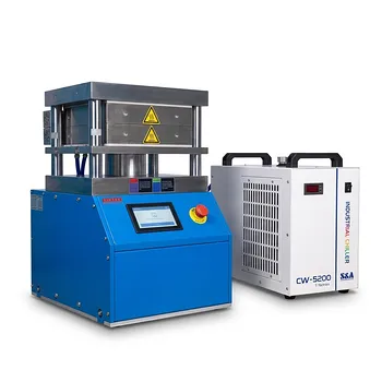
KINTEK specializes in laboratory press machines, including systems designed for accurate electrical testing. Our expertise ensures your die setup provides the perfect balance of electrical insulation and mechanical strength for valid, reliable results.
Let us help you achieve true material characterization. Contact our experts today to discuss your specific laboratory pressing needs!
Visual Guide
Related Products
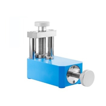
- Laboratory Hydraulic Press Lab Pellet Press Button Battery Press
- Laboratory Hydraulic Press 2T Lab Pellet Press for KBR FTIR
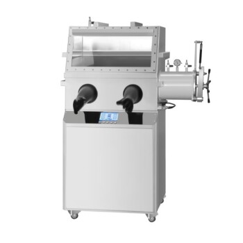
- Laboratory Hydraulic Press Lab Pellet Press Machine for Glove Box
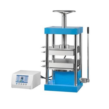
- Laboratory Split Manual Heated Hydraulic Press Machine with Hot Plates
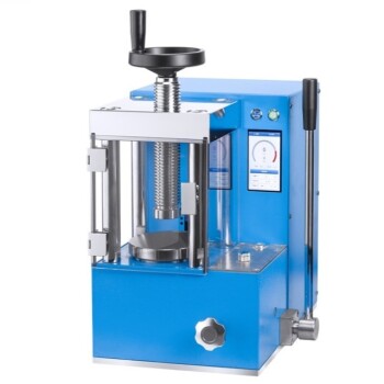
- Laboratory Hydraulic Pellet Press for XRF KBR FTIR Lab Press
People Also Ask
- Why is the temperature control precision of a lab hydraulic press critical in micro-structure thermal forming?
- How do laboratory hydraulic presses differ from industrial hydraulic presses? Precision vs. Power for Your Needs
- Why is a laboratory hydraulic press required for PBAT and PLA sample preparation? Achieve Flawless Characterization
- What is the role of a laboratory hydraulic press in the green body quality control? Master Your Sintering Trajectory
- How is a laboratory hydraulic press used for HAP composite gels? Master Mineral Substrate Standardization