The use of thick PET films effectively simulates rigid pressure processes by acting as a semi-rigid carrier that imposes uniform compression displacement on the Multilayer Ceramic Capacitor (MLCC) block. Specifically, films around 250 micrometers transmit pressure in a manner resembling plane strain, forcing the ceramic material to expand laterally and absorb internal electrode gaps under full constraint.
Core Takeaway By enforcing constant displacement rather than uniform pressure, thick PET films simulate a rigid pressing environment that exposes how differing deformation resistances within the MLCC block result in non-uniform internal density distributions.
The Mechanics of Rigid Simulation
Creating "Plane Strain" Conditions
In this configuration, the thick PET film acts as a boundary that restricts vertical freedom while transmitting force. This creates a stress state resembling plane strain, where the deformation is constrained largely to the cross-sectional plane of the MLCC block.
Enforcing Uniform Displacement
Unlike isostatic pressing, which applies uniform pressure from all directions, the PET film setup ensures uniform compression displacement. The film forces the entire top surface of the green block to move downward at the same rate, regardless of the material's resistance below it.
Simulating Hard Boundaries
This setup mimics a rigid body pressing environment. The film acts as a proxy for a rigid mold face, preventing the pressure medium from conforming to the slight irregularities of the block's surface.
Implications for Design and Analysis
Analyzing Differential Resistance
Because the displacement is constant, regions with different stiffness react differently. This allows researchers to observe non-uniform deformation between the internal electrode sections (which are stiffer) and the side-gap regions (which are softer).
Optimizing Electrode Gaps
Under these rigid conditions, the ceramic dielectric layers are forced to expand and flow. This simulation is vital for observing how dielectric expansion absorbs internal electrode gaps, providing data necessary to optimize the electrode area design for higher density.
Practical Benefits and Trade-offs
Mold Surface Protection
Beyond simulation mechanics, thick PET films serve a critical practical purpose. They act as a barrier that protects the mold surfaces from abrasion caused by the hard ceramic powders in the MLCC block.
The Trade-off of Rigidity
While this method is excellent for studying gap absorption, it produces a stress profile different from isostatic pressing. It highlights density gradients caused by geometric constraints rather than density gradients caused by pressure differentials.
Making the Right Choice for Your Goal
To apply these insights to your manufacturing or testing process, consider your specific analytical needs:
- If your primary focus is Electrode Design Optimization: Use thick PET films (approx. 250 $\mu$m) to force dielectric flow into electrode gaps, revealing the limits of your current geometry under full constraint.
- If your primary focus is Process Troubleshooting: Utilize the uniform displacement characteristic to identify side-gap regions that are under-densified due to lower deformation resistance compared to the active area.
Thick PET films are not just protective layers; they are boundary control tools that allow you to isolate and analyze the mechanical behavior of internal MLCC structures.
Summary Table:
| Feature | Rigid Simulation (Thick PET Film) | Isostatic Pressing Comparison |
|---|---|---|
| Primary Mechanic | Uniform Compression Displacement | Uniform Applied Pressure |
| Stress State | Plane Strain Conditions | Isotropic Stress State |
| Surface Interaction | Mimics rigid mold face/hard boundary | Conforms to block irregularities |
| Material Behavior | Forces dielectric flow into electrode gaps | Applies even force across all surfaces |
| Primary Benefit | Analyzes internal density gradients | Ensures high overall density uniformity |
Elevate Your Battery and MLCC Research with KINTEK
Precise pressure control is critical for optimizing internal electrode structures and material density. At KINTEK, we specialize in comprehensive laboratory pressing solutions designed to meet the rigorous demands of advanced material science.
Whether you need manual, automatic, heated, or multifunctional models, or require specialized cold and warm isostatic presses, our equipment delivers the reliability and precision your research deserves.
Maximize your lab's efficiency and data accuracy today—Contact KINTEK for a customized pressing solution!
References
- Fumio NARUSE, Naoya TADA. OS18F003 Deformation Behavior of Multilayered Ceramic Sheets with Printed Electrodes under Compression. DOI: 10.1299/jsmeatem.2011.10._os18f003-
This article is also based on technical information from Kintek Press Knowledge Base .
Related Products
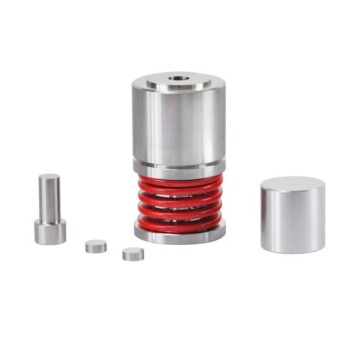
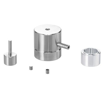
- Lab Round Bidirectional Press Mold
- Warm Isostatic Press for Solid State Battery Research Warm Isostatic Press
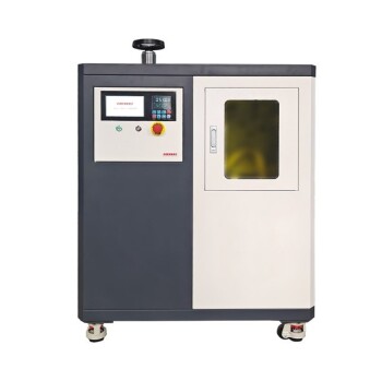
- Electric Lab Cold Isostatic Press CIP Machine
- Laboratory Hydraulic Split Electric Lab Pellet Press
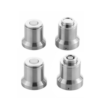
- Lab Button Battery Disassembly and Sealing Mold
People Also Ask
- What is the purpose of incorporating cartridge heaters into a lab press mold for MLCC block compression? Optimize Results
- What are the requirements for pressing molds when using SSCG? Key Materials for Complex Single Crystal Production
- What role do precision positioning and pressure molds play in single-lap joints? Ensure 100% Data Integrity
- What is the function of a pressing tool in thermoplastic panels? Master Precision Shaping & Fusion Bonding
- Why is a high-performance laboratory molding press critical for in-situ electrolyte formation? Unlock Battery Success