The diameter-to-thickness ratio of greater than 5:1 is critical when preparing phosphate sample discs to ensure the validity of electrical measurements. By adhering to this geometric standard, you minimize edge effects and stray capacitance, which are primary sources of error when characterizing materials with an impedance analyzer. This ratio guarantees a uniform electric field distribution, allowing for the accurate calculation of properties like the dielectric constant.
Core Takeaway To obtain precise electrical data, a sample must resemble an ideal parallel plate capacitor. A diameter-to-thickness ratio exceeding 5:1 reduces geometric distortions in the electric field, ensuring that measured values reflect the true material properties rather than artifacts of the sample's shape.
The Physics of Measurement Accuracy
Minimizing Edge Effects
When a voltage is applied across a sample disc, the electric field should ideally be straight and uniform between the electrodes. However, at the edges of the sample, the field lines tend to curve outward.
This phenomenon, known as the "fringing field" or edge effect, artificially inflates the measured capacitance. By keeping the sample diameter significantly larger than its thickness (the > 5:1 ratio), you reduce the proportion of the sample affected by these distorted fields.
Eliminating Stray Capacitance
Stray capacitance refers to unwanted charge storage that occurs outside the direct path between the electrodes. It introduces noise and error into your impedance data.
A high diameter-to-thickness ratio helps confine the electric field within the bulk of the phosphate material. This isolation ensures that the impedance analyzer measures the sample's response, not the parasitic effects of the surrounding environment.
Uniform Electric Field Distribution
Accurate calculation of the dielectric constant assumes that the electric field is uniform throughout the sample volume.
If the sample is too thick relative to its width, the field becomes non-uniform. This inconsistency leads to erroneous data points, making it impossible to reliably characterize the electrical behavior of the phosphate glass or ceramic.
Common Pitfalls to Avoid
The "Thicker is Stronger" Trap
It is tempting to create thicker discs to prevent cracking during the pressing or handling process. However, increasing thickness without proportionally increasing the diameter immediately violates the 5:1 ratio.
While a thicker sample is mechanically more robust, it renders the resulting electrical data scientifically invalid due to field distortion.
Inconsistent Pressing Density
While the geometric ratio is paramount, the laboratory press must also apply force evenly.
If the press produces a disc with varying thickness (a wedge shape), the ratio will fluctuate across the sample. This lack of parallelism disrupts the uniformity of the electric field just as severely as a poor aspect ratio.
Making the Right Choice for Your Goal
Achieving the correct geometry is a balancing act between physical constraints and theoretical requirements. Here is how to prioritize based on your specific needs:
- If your primary focus is High-Precision Dielectric Data: Prioritize a thinner sample profile to maximize the ratio, accepting that the disc will be more fragile and difficult to handle.
- If your primary focus is Mechanical Durability: Increase the diameter of your mold to allow for a thicker sample while still maintaining the critical > 5:1 ratio.
The geometry of your sample is not just a physical dimension; it is a fundamental component of your measurement instrument.
Summary Table:
| Parameter | Impact of Ratio > 5:1 | Consequence of Low Ratio (< 5:1) |
|---|---|---|
| Electric Field | Uniform and straight | Non-uniform (fringing fields) |
| Edge Effects | Minimized for high accuracy | Inflates measured capacitance |
| Stray Capacitance | Effectively eliminated | Increases noise and data error |
| Data Validity | Reflects true material properties | Includes geometric artifacts |
| Measurement Accuracy | High (Ideal parallel plate model) | Low (Erroneous dielectric constant) |
Elevate Your Materials Research with KINTEK
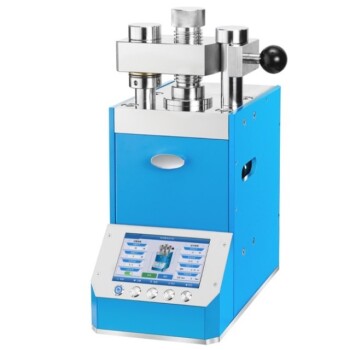
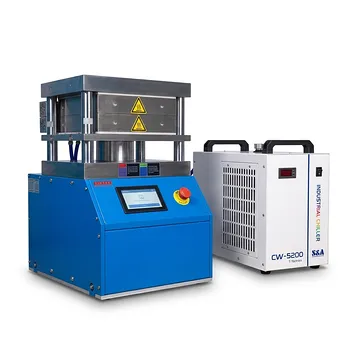
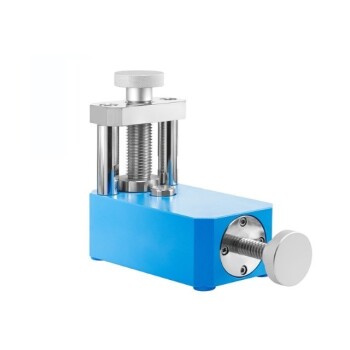
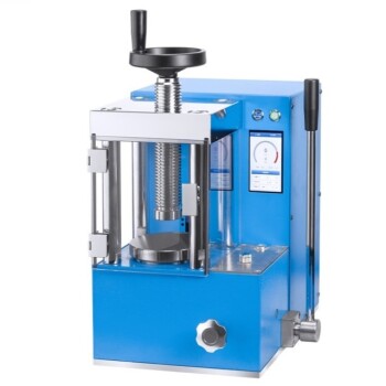
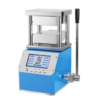
Precise sample geometry is the foundation of reliable electrical characterization. KINTEK specializes in comprehensive laboratory pressing solutions, offering manual, automatic, heated, multifunctional, and glovebox-compatible models, as well as cold and warm isostatic presses widely applied in battery and phosphate research.
Our precision-engineered molds and presses ensure the uniform density and exact diameter-to-thickness ratios required for high-precision dielectric data. Don't let geometric artifacts compromise your results—contact us today to find the perfect pressing solution for your lab's needs!
References
- Mohamed M. Gomaa. Temperature and AC electrical properties effects on phosphate natural mixture, Abu Tartur plateau, Western Desert, Egypt. DOI: 10.1038/s41598-025-09313-3
This article is also based on technical information from Kintek Press Knowledge Base .
Related Products
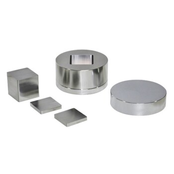
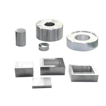
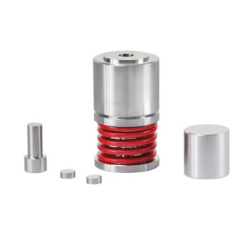
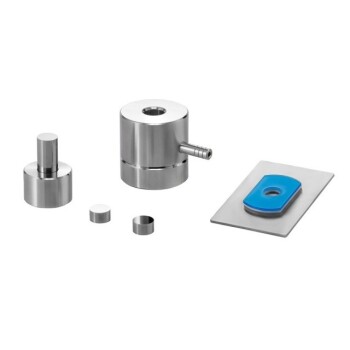
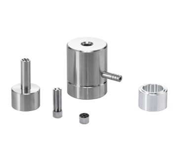
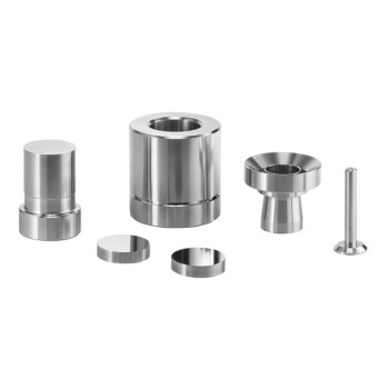
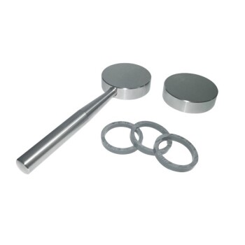
- Square Lab Press Mold for Laboratory Use
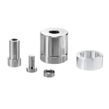
- Lab Ring Press Mold for Sample Preparation
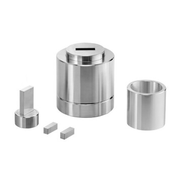
- Assemble Square Lab Press Mold for Laboratory Use
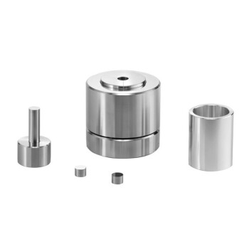
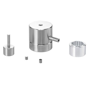
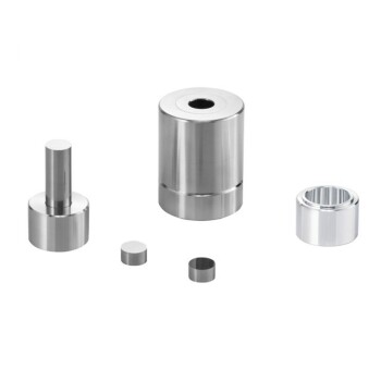
- Assemble Lab Cylindrical Press Mold for Laboratory Use
- Lab Cylindrical Press Mold for Laboratory Use
People Also Ask
- What role do precision positioning and pressure molds play in single-lap joints? Ensure 100% Data Integrity
- Why are precision laboratory molds essential for forming basalt-reinforced lightweight concrete specimens?
- What is the purpose of incorporating cartridge heaters into a lab press mold for MLCC block compression? Optimize Results
- How do the design and geometric precision of pressing molds and mandrels affect the quality of PTFE composite samples?
- Why is precise cooling management of the lab press mold necessary? Protect Core Integrity in Thermoforming