At its core, a hydraulic press uses a confined, incompressible fluid to convert a small input force into a massive output force. This is achieved with two interconnected cylinders of different sizes: a small one (the plunger) where force is applied, and a large one (the ram) that delivers the amplified force to a workpiece. The entire system operates on a fundamental principle of fluid dynamics.
The power of a hydraulic press doesn't come from the pistons themselves, but from the physics they exploit. By applying pressure to a confined fluid, you can multiply force based on the difference in piston size, turning a modest effort into a powerful output.

The Principle of Force Multiplication: Pascal's Law
The entire operation of a hydraulic press is governed by a single, elegant concept discovered in the 17th century.
What is Pascal's Law?
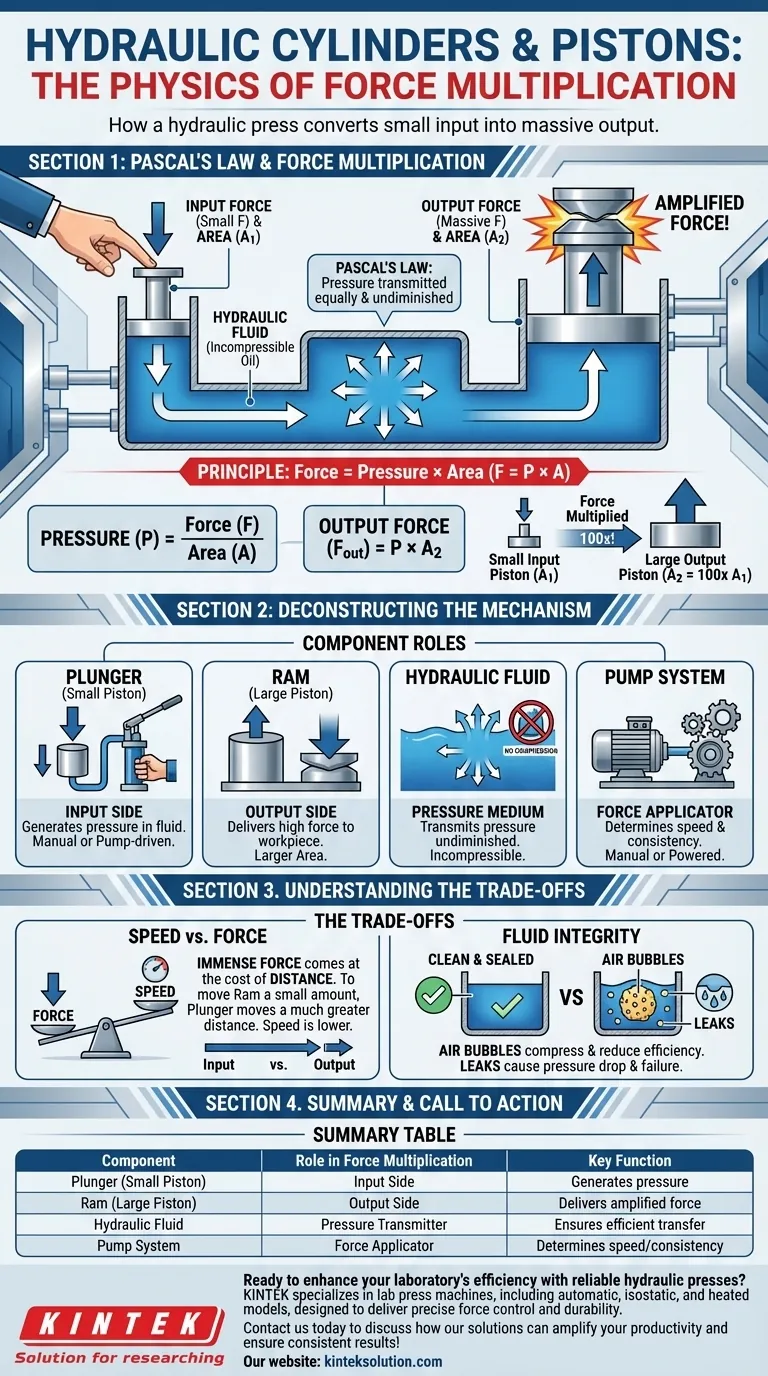
Pascal's Law states that when pressure is applied to a fluid in a confined space, that pressure is transmitted equally and undiminished in all directions throughout the fluid.
Imagine squeezing a water-filled balloon. The pressure you apply with your fingers is felt uniformly across the entire inner surface of the balloon, not just where you are pressing. Hydraulic fluid in a sealed press behaves the same way.
From Pressure to Force
Pressure is defined as Force applied over an Area (P = F/A). When a small force is applied to the small input piston (the plunger), it creates pressure in the hydraulic oil.
Because of Pascal's Law, this exact same pressure is exerted on the much larger output piston (the ram). However, because the ram has a significantly larger surface area, the resulting force is magnified. The output force is calculated as Force = Pressure × Area (F = P × A).
Why Piston Size is Everything
This relationship is the key to force multiplication. If the ram's surface area is 100 times larger than the plunger's, the output force will be 100 times greater than the input force.
This is how a simple hand-pumped press can generate many tons of force, allowing an operator to shape or stamp metal with minimal physical effort.
Deconstructing the Hydraulic Press Mechanism
A hydraulic press is a system where each component has a distinct role in achieving this force multiplication.
The Plunger (Small Piston)
This is the input side of the system. A relatively small mechanical force is applied to this piston, either manually with a lever or automatically via a pump. Its purpose is solely to generate pressure within the hydraulic fluid.
The Ram (Large Piston)
This is the output side of the system. It has a much larger surface area than the plunger. As the pressurized fluid pushes against it, it generates the high-output force used for pressing, molding, or crushing the workpiece.
The Hydraulic Fluid
Typically an incompressible oil, this fluid is the medium for transmitting pressure. Its inability to be easily compressed ensures that the pressure generated at the plunger is transferred to the ram with minimal loss of energy.
The Pump System
The method of applying force to the plunger determines the press's capability.
- Manual pumps are used for lower-force applications where speed is not critical.
- Electric or pneumatic pumps are used for industrial applications requiring large, consistent, and rapid force application.
Understanding the Trade-offs
While force multiplication seems almost magical, it comes with practical trade-offs that are critical to understand.
The Speed vs. Force Compromise
There is no free lunch in physics. The trade-off for immense force multiplication is distance.
To move the large ram a small distance (e.g., one inch), the small plunger must travel a much greater distance (e.g., 100 inches, using our earlier ratio). This is why high-tonnage presses can often seem slow in their operation.
The Critical Role of Fluid Integrity
The system's effectiveness depends entirely on the fluid being perfectly confined and incompressible.
Air bubbles in the fluid will compress under pressure, causing a spongy and inefficient transfer of force. Likewise, any leaks in the system will cause a drop in pressure and a failure to generate the required output force.
Making the Right Choice for Your Application
Understanding these principles allows you to evaluate a hydraulic press based on its intended function.
- If your primary focus is maximizing force: The ratio between the ram's area and the plunger's area is the most critical design factor to consider.
- If your primary focus is operational speed: A higher-volume pump is required, but you must accept the inverse relationship between speed and the force-multiplication ratio.
- If your primary focus is reliability and precision: A robust, perfectly sealed system with high-quality, clean hydraulic fluid is non-negotiable for consistent performance.
By understanding this mechanism, you can see the press not as brute machinery, but as an elegant and powerful application of fundamental physics.
Summary Table:
| Component | Role in Force Multiplication | Key Function |
|---|---|---|
| Plunger (Small Piston) | Input side for applying force | Generates pressure in hydraulic fluid |
| Ram (Large Piston) | Output side for amplified force | Delivers high force to workpiece |
| Hydraulic Fluid | Transmits pressure undiminished | Ensures efficient force transfer |
| Pump System | Applies force to plunger | Determines speed and consistency of operation |
Ready to enhance your laboratory's efficiency with reliable hydraulic presses? KINTEK specializes in lab press machines, including automatic, isostatic, and heated models, designed to deliver precise force control and durability for your research and testing needs. Contact us today to discuss how our solutions can amplify your productivity and ensure consistent results!
Visual Guide
Related Products
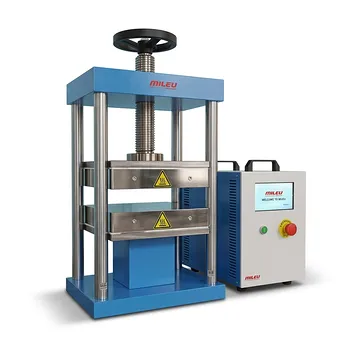
- Automatic High Temperature Heated Hydraulic Press Machine with Heated Plates for Lab
- Manual Heated Hydraulic Lab Press with Integrated Hot Plates Hydraulic Press Machine
- Heated Hydraulic Press Machine with Heated Plates for Vacuum Box Laboratory Hot Press
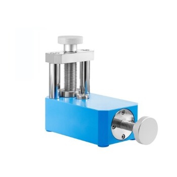
- Laboratory Hydraulic Press 2T Lab Pellet Press for KBR FTIR
- Laboratory Hydraulic Press Lab Pellet Press Machine for Glove Box
People Also Ask
- Why is a heated laboratory hydraulic press necessary for PVC test specimens? Ensure Precise Tensile & Rheology Data
- What are the industrial applications of heated hydraulic presses? Master Heat & Force for Precision Manufacturing
- What are the advantages of adding a heating element to a hydraulic press? Unlock Advanced Material Synthesis
- What role does a heated hydraulic press play in material testing and research? Essential Insights for Lab Innovation
- How does a laboratory heated hydraulic press facilitate PBN sample prep for WAXS? Achieve Precise X-Ray Scattering