At its core, a hydraulic press operates using a set of fundamental components. These include the hydraulic cylinder assembly (which contains the pistons), a pump to create pressure, hydraulic fluid to transfer that pressure, and a strong mainframe to hold everything together. This system works as a unified whole to multiply force for industrial and workshop tasks.
The central takeaway is that a hydraulic press does not create energy, but rather multiplies force. It achieves this by using an incompressible fluid to convert a small, manageable force applied to a small piston into an immense force exerted by a much larger piston, all governed by a fundamental principle of fluid mechanics.
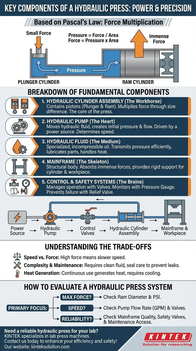
The Core Principle: Pascal's Law in Action
To understand the components, you must first understand the principle that connects them. The entire system is an application of Pascal's Law, which states that pressure applied to a confined fluid is transmitted equally in all directions.
The Concept of Force Multiplication
A hydraulic system uses two interconnected cylinders of different sizes. A small force is applied to the smaller "plunger" piston, which creates pressure in the fluid (Pressure = Force / Area).
Because this pressure is transmitted equally throughout the fluid, it acts on the larger "ram" piston. Since the ram has a much larger surface area, the resulting force it exerts is dramatically amplified (Force = Pressure x Area).
The Role of Incompressible Fluid
This force multiplication is only possible because the hydraulic fluid, typically a specialized oil, is virtually incompressible. It does not get squeezed into a smaller volume under pressure. Instead, it efficiently transfers the energy from the small piston to the large one.
Breakdown of Key Components and Their Functions
Each part of a hydraulic press has a distinct and critical role in achieving this force multiplication safely and controllably.
The Hydraulic Cylinder Assembly (The Workhorse)
This is where the magic of force multiplication physically occurs. It consists of two main parts:
- The plunger cylinder, which is small in diameter and receives the initial force.
- The ram cylinder, which is much larger in diameter and delivers the final, amplified pressing force.
Inside these cylinders are the pistons (or plungers and rams) that move and act upon the fluid or the workpiece. The size difference between these two pistons is the primary determinant of the press's force-multiplying power.
The Hydraulic Pump (The Heart)
The pump does the work of moving the hydraulic fluid from the reservoir into the cylinder system. Driven by a power source (usually an electric motor), the pump generates the fluid flow that creates the initial system pressure. The pump's capacity, measured in gallons or liters per minute, directly influences the operational speed of the press ram.
The Hydraulic Fluid (The Medium)
This specialized oil is the lifeblood of the system. Its primary job is to transmit pressure from the plunger to the ram. It is chosen for several key properties: thermal stability, lubrication of moving parts, and its near-incompressibility, which ensures efficient power transfer.
The Mainframe (The Skeleton)
The mainframe is the structural body of the press. It must be incredibly robust to absorb and contain the immense forces generated during operation. It holds the cylinder assembly in place and provides the rigid structure against which the ram presses the workpiece.
Control & Safety Systems (The Brains)
A press is more than just raw power; it requires precision and safety. These components manage the system:
- Control Valves: These direct the flow of hydraulic fluid, allowing an operator to extend the ram, retract it, or hold it in position.
- Pressure Gauge: This allows the operator to monitor the pressure within the system, ensuring it operates within its designed limits.
- Relief Valve: This is a critical safety device that automatically vents excess pressure if the system exceeds its maximum rating, preventing catastrophic failure.
Understanding the Trade-offs
While incredibly powerful, hydraulic systems are governed by physical trade-offs and have specific operational considerations.
Speed vs. Force
The fundamental trade-off in a hydraulic press is speed for force. To achieve massive force multiplication, the large ram piston must travel a much shorter distance for a given volume of fluid compared to the small plunger piston. This means high-force presses are often inherently slow.
System Complexity and Maintenance
Hydraulic systems require diligent maintenance. The hydraulic fluid must be kept clean and free of contaminants to prevent damage to the pump and seals. Leaks are a common point of failure and can reduce system efficiency and create safety hazards.
Heat Generation
The continuous movement and pressurization of hydraulic fluid generate heat. In heavy-duty industrial applications, this can degrade the fluid and affect performance. Many large presses incorporate heat exchangers or cooling systems to manage operating temperatures.
How to Evaluate a Hydraulic Press System
When choosing or designing a system, focus on the components that align with your primary goal.
- If your primary focus is maximum force: Pay closest attention to the ram cylinder's diameter and the system's maximum pressure rating (PSI).
- If your primary focus is operational speed: Examine the pump's flow rate (gallons per minute) and the responsiveness of the control valves.
- If your primary focus is reliability and safety: Prioritize the mainframe's construction quality, the presence of pressure relief valves, and ease of access for maintaining seals and fluid.
Understanding how each component contributes to the whole empowers you to select, operate, and maintain a hydraulic press effectively.
Summary Table:
| Component | Key Function |
|---|---|
| Hydraulic Cylinder Assembly | Multiplies force using pistons of different sizes |
| Hydraulic Pump | Generates pressure and fluid flow for system operation |
| Hydraulic Fluid | Transmits pressure and lubricates parts |
| Mainframe | Provides structural support and absorbs forces |
| Control & Safety Systems | Manages operation and prevents failures |
Need a reliable hydraulic press for your lab? KINTEK specializes in lab press machines, including automatic lab presses, isostatic presses, and heated lab presses, designed to deliver precise force control and durability for your laboratory needs. Contact us today to enhance your efficiency and safety with our expert solutions!
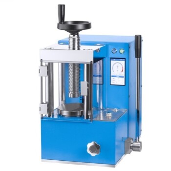
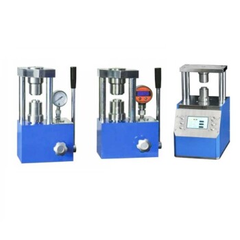
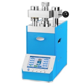
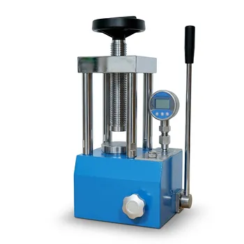
Visual Guide
Related Products
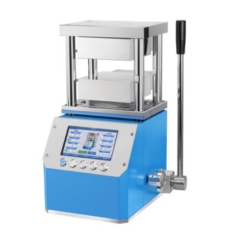
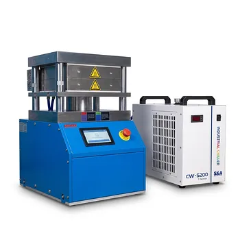
- Automatic High Temperature Heated Hydraulic Press Machine with Heated Plates for Lab
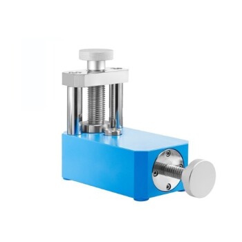
- Manual Heated Hydraulic Lab Press with Integrated Hot Plates Hydraulic Press Machine
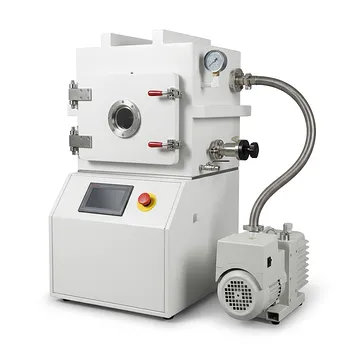
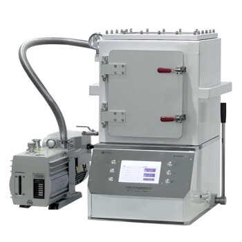
- Heated Hydraulic Press Machine with Heated Plates for Vacuum Box Laboratory Hot Press
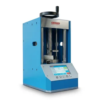
- Laboratory Hydraulic Press 2T Lab Pellet Press for KBR FTIR
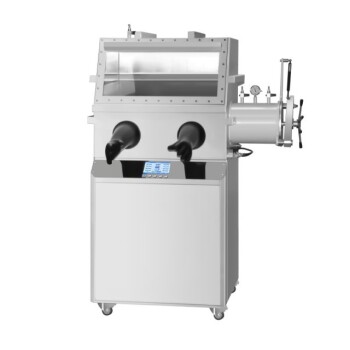
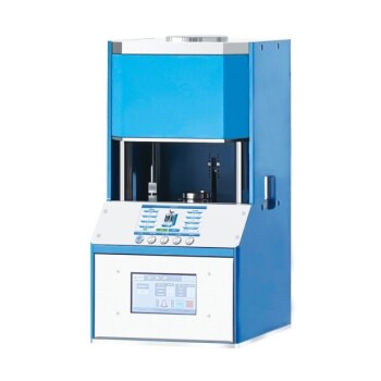
- Laboratory Hydraulic Press Lab Pellet Press Machine for Glove Box
People Also Ask
- How is the temperature of the hot plate controlled in a hydraulic lab press? Achieve Thermal Precision (20°C-200°C)
- How does a laboratory heated hydraulic press facilitate PBN sample prep for WAXS? Achieve Precise X-Ray Scattering
- Why is a laboratory hydraulic press with heating plates required for PLA/TEC films? Achieve Precise Sample Integrity
- What are the industrial applications of heated hydraulic presses? Master Heat & Force for Precision Manufacturing
- Why is a heated laboratory hydraulic press necessary for PVC test specimens? Ensure Precise Tensile & Rheology Data