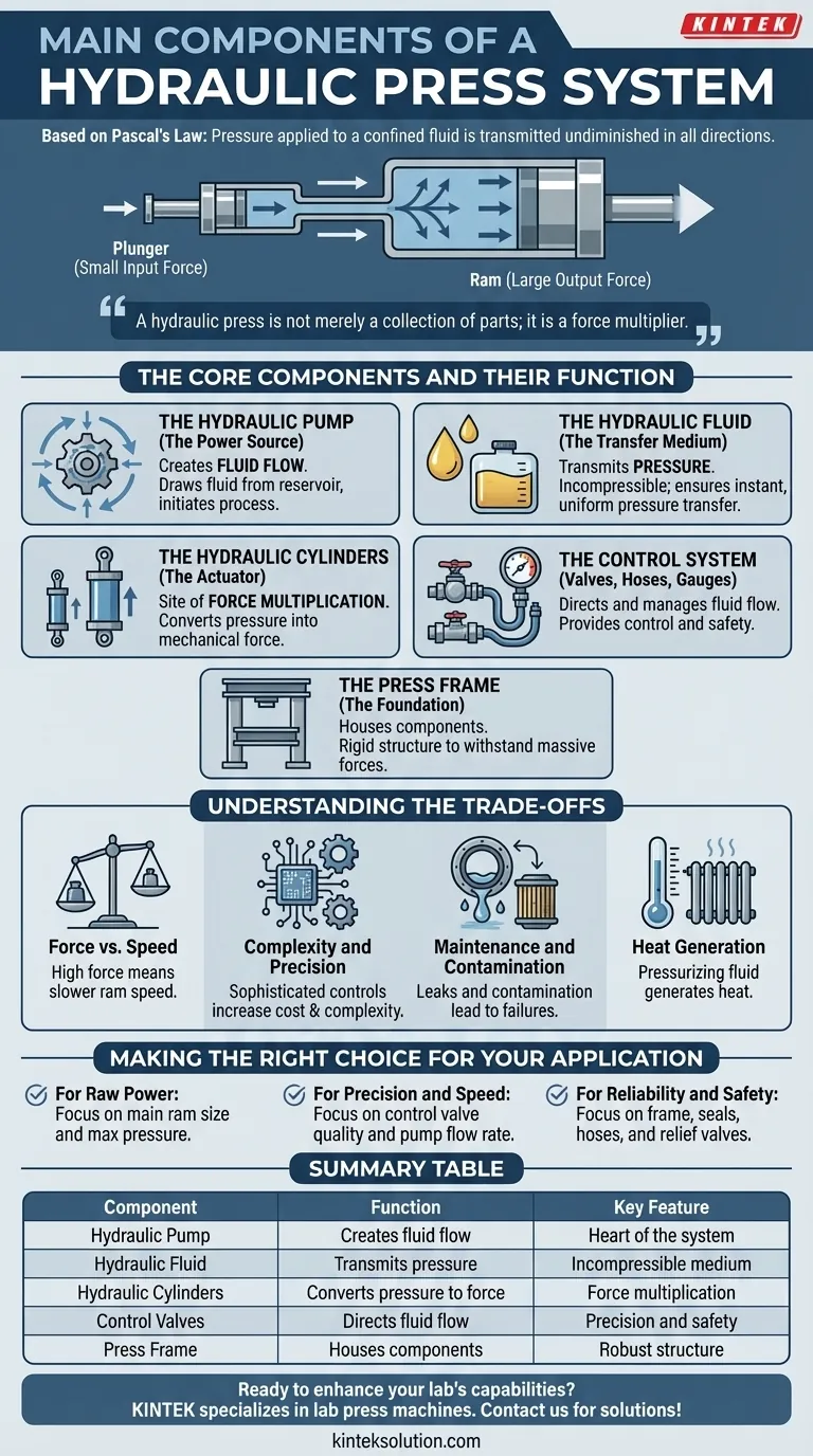
At its most fundamental level, a hydraulic press system is comprised of four primary components. These are the hydraulic pump which creates fluid flow, the hydraulic fluid (typically oil) which transmits pressure, one or more hydraulic cylinders which convert that pressure into mechanical force, and a system of control valves and hoses to direct and manage the fluid.
A hydraulic press is not merely a collection of parts; it is a force multiplier. By using an incompressible fluid to transfer pressure from a small area to a much larger one, it allows a minimal input effort to generate an immense and controllable output force.
The Core Components and Their Function
To truly understand a hydraulic press, think of it as a system where each component plays a distinct and critical role. The principle behind its operation, Pascal's Law, states that pressure applied to a confined fluid is transmitted undiminished in all directions. This is the key to its power.
The Power Source: The Hydraulic Pump
The pump is the heart of the system. Its job is not to create pressure, but to create fluid flow.
Pressure is only generated when this flow meets resistance, such as the load on the press ram. The pump draws fluid from a reservoir and forces it into the system, initiating the entire process.
The Transfer Medium: The Hydraulic Fluid
Hydraulic fluid, usually a specialized oil, acts as the system's blood. It is chosen for its incompressibility, meaning it does not noticeably shrink under pressure.
This property ensures that the pressure generated by the pump is transferred instantly and uniformly throughout the entire circuit, from the smallest hose to the largest cylinder.
The Actuator: The Hydraulic Cylinders
The cylinders are the muscles of the system and the site of force multiplication. A press typically has at least two cylinders of different sizes connected by the fluid.
A small input force is applied to a small piston (the plunger). This generates pressure in the fluid. That same pressure then acts on a much larger piston (the ram), which produces a proportionally larger output force. The ratio of the pistons' areas determines the force multiplication factor.
The Control System: Valves, Hoses, and Gauges
This is the nervous system, providing control and safety. Control valves direct the flow of fluid, allowing the operator to extend, retract, or hold the position of the main ram with precision.
Hoses and pipes are the veins and arteries, securely transporting the high-pressure fluid between components. Pressure relief valves are a critical safety feature, preventing over-pressurization that could damage the system or create a hazard.
The Foundation: The Press Frame
Often overlooked, the mainframe is the skeleton. It is the rigid structure that houses all the components and must be strong enough to withstand the massive forces it is designed to generate. Without a robust frame, the press would simply push itself apart.
Understanding the Trade-offs
A hydraulic press is an elegant solution for generating high force, but its design involves balancing several key factors.
Force vs. Speed
There is an inherent trade-off between the amount of force multiplication and the speed of the ram. A system designed for extremely high force (with a very large ratio between piston sizes) will move the ram much more slowly for a given fluid flow rate.
Complexity and Precision
A simple press may only have basic manual controls. However, achieving high-speed, repeatable, and precise operations requires sophisticated proportional valves, electronic controls, and feedback sensors, significantly increasing system complexity and cost.
Maintenance and Contamination
Hydraulic systems are powerful but sensitive. The primary failure points are often leaks in seals and hoses. Furthermore, contamination of the hydraulic fluid with dirt or water can rapidly degrade components like pumps and valves, leading to poor performance and costly repairs.
Heat Generation
The process of moving and pressurizing fluid generates heat. In high-duty cycle applications, this heat must be managed with coolers or heat exchangers to prevent the fluid from breaking down and to maintain system efficiency.
Making the Right Choice for Your Application
Understanding these components helps you evaluate a hydraulic press based on your specific needs.
- If your primary focus is raw power: The size of the main ram cylinder and the system's maximum pressure rating are the most critical specifications.
- If your primary focus is precision and speed: The quality and type of control valves, along with the pump's flow rate, will define the press's performance and responsiveness.
- If your primary focus is reliability and safety: Pay close attention to the quality of the frame, seals, and hoses, and ensure the system includes a properly functioning pressure relief valve.
By seeing the system as an interconnected whole, you can move beyond a simple list of parts to truly appreciate and leverage the power of hydraulic force.
Summary Table:
| Component | Function | Key Feature |
|---|---|---|
| Hydraulic Pump | Creates fluid flow | Heart of the system |
| Hydraulic Fluid | Transmits pressure | Incompressible medium |
| Hydraulic Cylinders | Converts pressure to force | Force multiplication |
| Control Valves | Directs fluid flow | Precision and safety |
| Press Frame | Houses components | Robust structure |
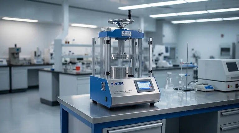
Ready to enhance your lab's capabilities with a reliable hydraulic press? KINTEK specializes in lab press machines, including automatic, isostatic, and heated models, designed to deliver precise force control and durability for your laboratory needs. Contact us today to discuss how our solutions can boost your efficiency and safety!
Visual Guide
Related Products
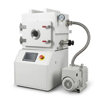
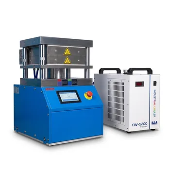
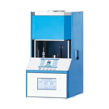
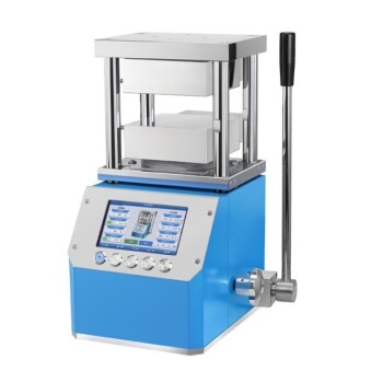
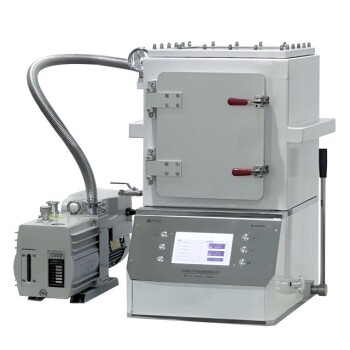
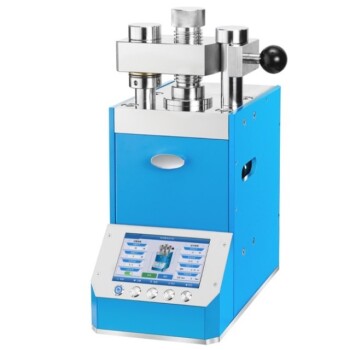
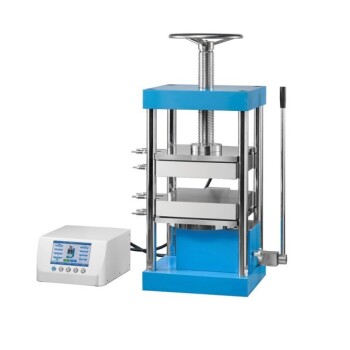
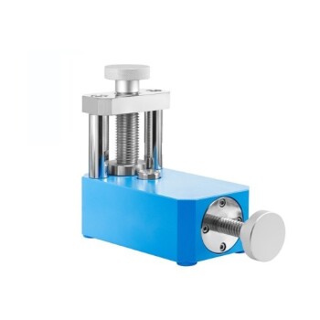
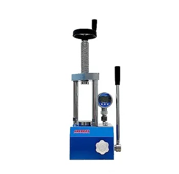
- Heated Hydraulic Press Machine with Heated Plates for Vacuum Box Laboratory Hot Press
- Automatic High Temperature Heated Hydraulic Press Machine with Heated Plates for Lab
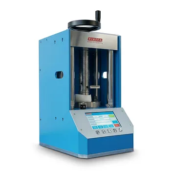
- Automatic Heated Hydraulic Press Machine with Hot Plates for Laboratory
- Automatic Heated Hydraulic Press Machine with Heated Plates for Laboratory
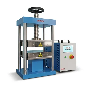
- Manual Heated Hydraulic Lab Press with Integrated Hot Plates Hydraulic Press Machine
People Also Ask
- What industrial applications does a heated hydraulic press have beyond laboratories? Powering Manufacturing from Aerospace to Consumer Goods
- How does a laboratory heated hydraulic press reshape phosphoric acid-based vitrimers? Master the Reprocessing Cycle
- What are the essential functions of a heated laboratory hydraulic press? Mastering HTM Coupling in Rock Mechanics
- What are the advantages of having a heating element in a hydraulic press? Unlock Precision in Material Processing
- How does a heated laboratory hydraulic press facilitate the construction of composite lithium metal anodes? Mastering Molten Lithium Infiltration