Industrial hydraulic jacks establish a controlled loading environment essential for precise structural testing. They provide a continuous and stable uplift rate to the steel rock bolt by utilizing precisely controlled oil pressure. This stability is critical for accurately observing the bolt's behavior as it transitions from a stable state into structural failure.
By maintaining a steady uplift rate through regulated oil pressure, hydraulic jacks ensure that data regarding the transition from elastic deformation to non-linear failure is accurate, reliable, and free from dynamic distortion.
The Mechanics of Load Application
Precision via Oil Pressure
The fundamental condition provided by the equipment is precisely controlled oil pressure. This mechanism allows the operator to regulate the force applied to the bolt with high exactitude, ensuring the test conditions remain consistent throughout the experiment.
Continuous Stability
Unlike methods that might apply load in uneven bursts, industrial hydraulic jacks ensure a continuous and stable uplift rate. This constant application of force is necessary to isolate the rock bolt's static performance without the interference of sudden acceleration or shock.
Capturing Critical Phases of Failure
The Pseudo-Elastic Phase
The controlled loading rate allows for the clear identification of the pseudo-elastic phase. In this initial stage, the system deforms under stress but behaves predictably, a critical baseline for analyzing structural integrity.
Transition to Non-Linear Failure
Most importantly, the equipment clearly demonstrates the transition into the non-linear failure phase. This is the point where the system moves beyond elastic recovery, providing engineers with a detailed view of how and when the bolt begins to fail permanently.
Understanding the Limits and Trade-offs
Dependence on Pressure Regulation
The validity of the test data is strictly tied to the control of oil pressure. If the pressure regulation system fails to maintain consistency, the uplift rate will fluctuate, rendering the data regarding the transition phases unreliable.
Scope of Simulation
This method is optimized for determining ultimate bearing capacity under static conditions. It specifically targets the observation of rock cone failure morphology, meaning it may not fully replicate dynamic or high-speed impact scenarios found in other geological events.
Making the Right Choice for Your Goal
To maximize the value of your pull-out tests, align your experimental setup with your specific data requirements.
- If your primary focus is determining load limits: Ensure your hydraulic system is calibrated to maintain absolute pressure stability to accurately pinpoint the ultimate bearing capacity.
- If your primary focus is studying failure mechanics: Utilize the continuous uplift rate to document the specific morphology of rock cone failure as the system exits the pseudo-elastic phase.
Precision in pressure control is the defining factor that turns raw force into actionable engineering data.
Summary Table:
| Condition Provided | Description | Impact on Test Quality |
|---|---|---|
| Precise Oil Pressure | Regulated force application | Ensures consistent and repeatable test conditions |
| Continuous Uplift Rate | Stable, non-burst loading | Isolates static performance and prevents dynamic distortion |
| Pseudo-Elastic Control | Controlled deformation monitoring | Establishes a predictable baseline for structural integrity |
| Failure Transition | Clear non-linear phase mapping | Accurate identification of the point of permanent structural failure |
Elevate Your Material Testing Precision with KINTEK
Precise pressure control is the difference between raw data and actionable engineering insights. KINTEK specializes in comprehensive laboratory pressing solutions, offering a versatile range of manual, automatic, heated, and multifunctional models, alongside advanced cold and warm isostatic presses optimized for battery research and structural testing.
Whether you are determining ultimate bearing capacity or studying complex rock cone failure morphology, our equipment delivers the stability and precision your research demands.
Ready to optimize your laboratory's testing capabilities? Contact KINTEK today to find the perfect pressing solution for your specific application.
References
- Cristobal Javier Manquehual, Leif Lia. 3D Numerical Modeling of Rock Mass Failure in an Uplift Test of a Rock Anchor with Focus on the Role of Rock Joints. DOI: 10.1007/s00603-024-04315-5
This article is also based on technical information from Kintek Press Knowledge Base .
Related Products
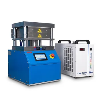
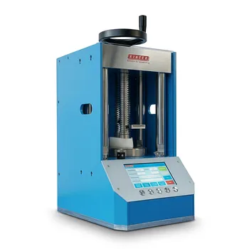
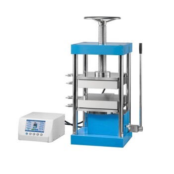
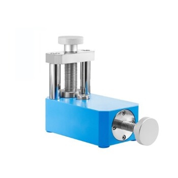
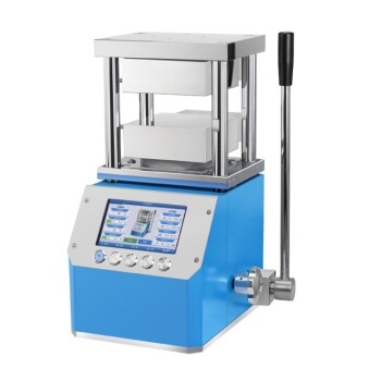
- Heated Hydraulic Press Machine with Heated Plates for Vacuum Box Laboratory Hot Press
- Automatic Heated Hydraulic Press Machine with Heated Plates for Laboratory
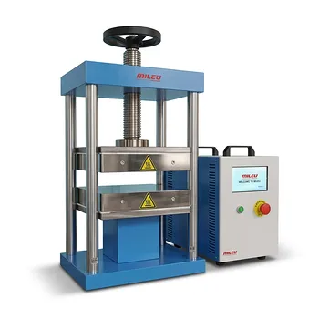
- Heated Hydraulic Press Machine With Heated Plates For Vacuum Box Laboratory Hot Press
- Automatic High Temperature Heated Hydraulic Press Machine with Heated Plates for Lab
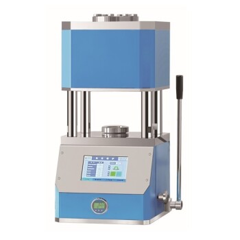
- Automatic Heated Hydraulic Press Machine with Hot Plates for Laboratory
People Also Ask
- How does a heated laboratory hydraulic press facilitate the construction of composite lithium metal anodes? Mastering Molten Lithium Infiltration
- What are the advantages of having a heating element in a hydraulic press? Unlock Precision in Material Processing
- How does a laboratory heated hydraulic press reshape phosphoric acid-based vitrimers? Master the Reprocessing Cycle
- How are heated hydraulic presses utilized in the preparation of thin films? Key Mechanisms and Applications
- What industrial applications does a heated hydraulic press have beyond laboratories? Powering Manufacturing from Aerospace to Consumer Goods