The capillary tube acts as the system’s primary flow restrictor. In a decompression speed regulator utilizing a piston structure, this tube forces the pressurized medium to pass through an extremely small diameter during the discharge phase. This physical bottleneck generates significant fluid resistance, which directly governs the rate at which the piston resets and pressure is released.
The capillary tube converts the kinetic energy of the flowing medium into fluid resistance, creating a calculated pressure loss. This mechanism transforms what would be a violent discharge into a smooth, gradual pressure drop, essential for the longevity of the machine's components.
The Mechanics of Controlled Decompression
Generating Fluid Resistance
The core function of the capillary tube is to create an intentional obstacle in the flow path. As the piston resets under discharge pressure, it attempts to push the medium out rapidly. By forcing this volume through the extremely small diameter of the capillary tube, the system induces high friction and turbulence.
Regulating Piston Velocity
This resistance acts as a brake on the piston's movement. Without the tube, the piston would reset instantly, leading to a rapid dump of pressure. The capillary tube ensures the flow rate is artificially slowed, linking the physical movement of the mechanical piston to the flow capacity of the tube.
Why This Restriction is Critical
Preventing Violent Fluctuations
High-pressure systems store immense potential energy. If this energy is released instantaneously, it creates shockwaves and violent pressure fluctuations within the system. The capillary tube smooths out this curve, ensuring the transition from high to low pressure is linear rather than abrupt.
Protecting the Anvil Components
The primary beneficiary of this regulated speed is the equipment itself, specifically the expensive anvil components. Sudden depressurization acts like a hammer blow to these precision parts. By enforcing a gradual pressure drop, the capillary tube eliminates the mechanical shock that leads to premature failure or cracking of the anvil.
Understanding the Trade-offs
Sensitivity to Blockages
Because the system relies on an extremely small diameter to generate resistance, it is inherently vulnerable to contamination. Even minor particulate matter in the medium can obstruct the tube. A blockage here disrupts the entire decompression cycle, potentially trapping pressure or causing erratic regulation.
Fixed Decompression Rates
The flow rate is defined by the physical geometry of the tube. Unlike a variable valve, a capillary tube offers a fixed resistance profile. This means the decompression speed is hard-set by the tube's dimensions and cannot be adjusted dynamically during operation without changing the component itself.
Ensuring System Longevity
The capillary tube is not just a connector; it is a safety device that prioritizes equipment survival over speed. When evaluating your system's performance, consider the following:
- If your primary focus is Equipment Life: Prioritize a capillary tube specification that ensures the slowest acceptable pressure drop to maximize protection for the anvil.
- If your primary focus is Maintenance Reliability: Ensure the medium is rigorously filtered, as the small diameter of the tube makes the regulator highly susceptible to clogging.
The capillary tube is the defining variable that balances the physics of pressure release with the mechanical limits of your hardware.
Summary Table:
| Feature | Function in Decompression | Primary Benefit |
|---|---|---|
| Flow Restriction | Creates bottleneck via small diameter | Generates controlled fluid resistance |
| Piston Braking | Artificially slows resetting speed | Prevents violent pressure fluctuations |
| Energy Conversion | Converts kinetic energy to pressure loss | Smooths the decompression curve |
| Hardware Protection | Eliminates sudden mechanical shock | Protects expensive anvil components |
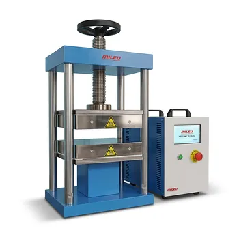
Optimize Your Lab’s Precision with KINTEK Pressing Solutions
Protect your critical research and extend the life of your expensive anvil components with KINTEK’s advanced laboratory pressing technology. Whether you are conducting battery research or material synthesis, our comprehensive range of manual, automatic, heated, and isostatic presses are engineered for maximum stability and controlled decompression.
Don't let violent pressure drops compromise your results or damage your equipment. Contact KINTEK today to find the perfect glovebox-compatible or multifunctional pressing solution tailored to your laboratory's needs!
References
- Tatsuya Maejima. Pressure Test Equipment and High Pressure Equipment. DOI: 10.4131/jshpreview.28.28
This article is also based on technical information from Kintek Press Knowledge Base .
Related Products
- Laboratory Hydraulic Press Lab Pellet Press Machine for Glove Box
- Manual Laboratory Hydraulic Press Lab Pellet Press
- Heated Hydraulic Press Machine with Heated Plates for Vacuum Box Laboratory Hot Press
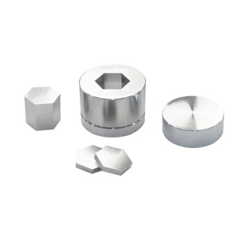
- Special Shape Lab Press Mold for Laboratory Applications
- Automatic High Temperature Heated Hydraulic Press Machine with Heated Plates for Lab
People Also Ask
- What is the function of a laboratory hydraulic press for KBr pellets? Achieving Perfect FTIR Infrared Spectroscopy
- How does the application of a laboratory hydraulic press improve the performance of Tungsten Trioxide (WO3) electrodes? - Pro Tips
- Why is precise pressure control from a laboratory hydraulic press necessary for Si-Ge battery electrodes?
- Why use a laboratory hydraulic press for rock axial compression tests? Master Fracture Research & Mechanics
- What role does a laboratory hydraulic press play in reaction pellets? Optimizing Lunar Soil and Metal Fuel Density